Better than a quicker burn...
...is a burn which gradually grows in amplitude over time.

Regarding…
A Quicker Burn

https://tinyurl.com/quickerburn is a simple simulation of an overunity circuit which takes thousands of years to show any appreciable results. It’s called “quicker” since it’s faster than a https://t…
…a better option would be a gradual amplification towards infinity regulated by several factors.
To prevent an immediate explosion, a spark gap is included to slow down the amplification of power.
This spark gap is not an ordinary spark gap. In fact, it's not even an ordinary gas discharge tube such as a neon bulb or a fluorescent tube.
Instead, it is a noble gas discharge tube but with finally divided carbon powder suspended within this noble gas to short out the two internal electrodes by reducing the quantity of voltage that is required to break down the resistance that the noble gas possesses against an applied voltage. Otherwise, without this carbon powder acting as a short circuit, the circuit (to which this tube is attached) would blow up, immediately.
This type of spark gap will eventually light up but will not alter the behavior of the circuit a whole lot (at least not to any degree that I noticed under simulation).
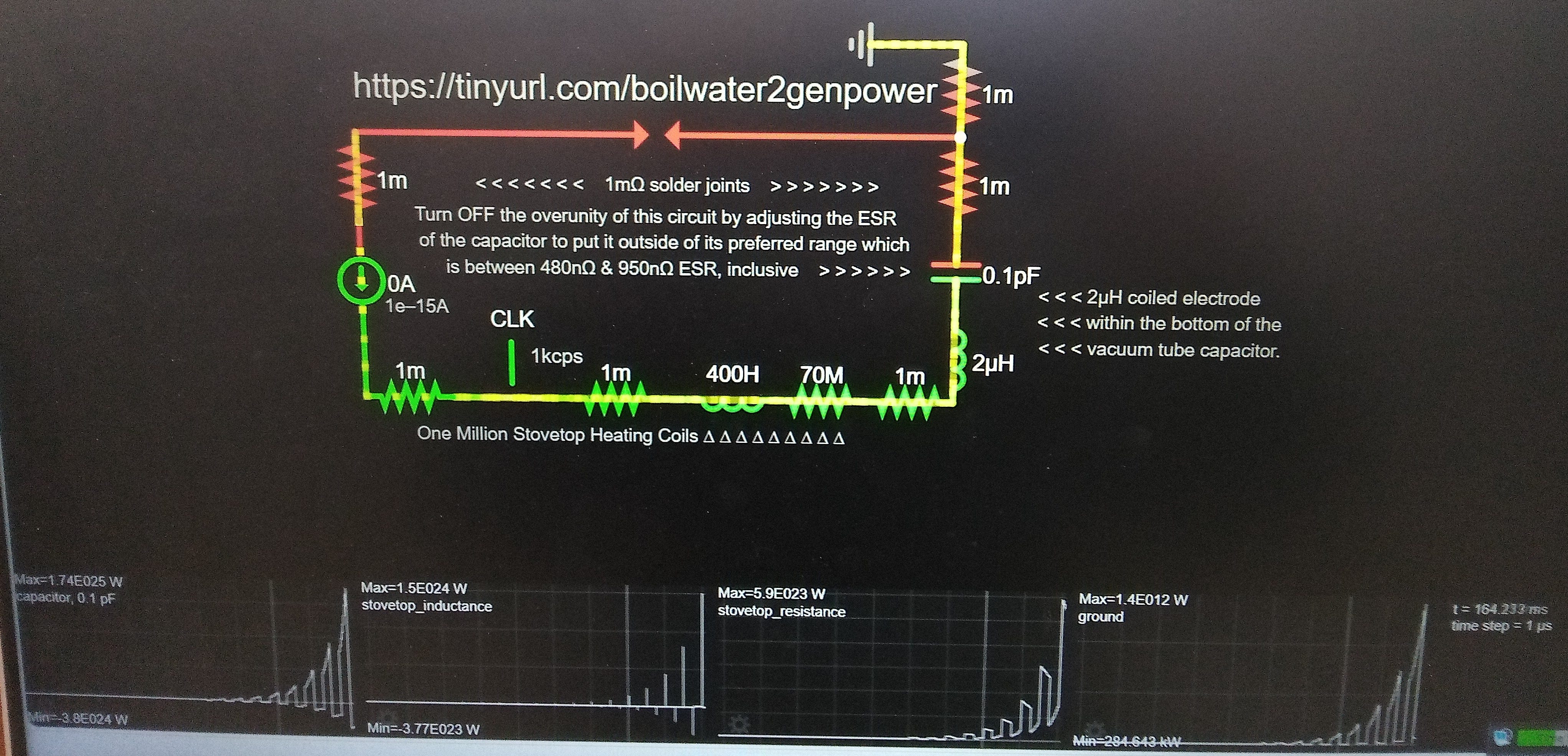
The capacitor possesses an Equivalent Series Resistance within a narrow band of tolerance in order to make it possible for the power to build up within this simple circuit. The value of this ESR is between 480 nano ohms and 950 nano ohms, inclusive.
By adjusting the ESR of this circuit’s capacitor, it may be possible to turn OFF the overunity gain mode and replace it with an entropic decline mode.
The type of overunity circuits which I study under simulation tend to be explosive. So, it’s not easy for my circuits to be stable. In fact, they appear to be incapable of achieving stability such as what we’ve become accustomed to with all of our appliances and our electric utility grid.
But our customary circuits are stable at the cost of our having to pay exorbitant rates for our electrical power in order to maintain that stability.
So, my type of circuit simulation saves the customer money on their bill. This upholds power production, but at the cost of rigorous stability.
Another requirement is the inclusion of a switch which is driven by a clock timer operating at a frequency of a thousand cycles per second possessing a 50% duty cycle. This will produce triangular waves of voltage within the capacitor at a stable amplitude if we don't try to modify the equivalent series resistance of the capacitor.
The coil is serving as an inductive load – although I would not expect it to operate as a motor coil, because the wattage waveforms are spikes which don't satisfy the requirements of motor coils which expect a sine wave or a close equivalent.
If its resistance is raised beyond the standard resistance of motor coil windings to more closely reflect the resistance of stovetop electric range cooking coils (made of an alloy of nickel and chromium, called: nichrome), and if its inductance is lowered to more closely reflect the resistance of these types of heating elements, then this coil could represent an example of an inductive load within our common sense of experience.
How much resistance and how much inductance does a stovetop coil possess?
Google AI’s answer: A stovetop coil's resistance typically falls within the range of 20 to 120 ohms, while its inductance is usually in the range of microhenries (µH). The specific resistance and inductance values depend on factors like the coil's size, wattage, and the material of the heating element. [1, 2, 3, 4]
Here's a more detailed breakdown:
Resistance:
Range: Stovetop coil resistance can vary greatly but generally falls between 20 and 40 ohms for oven elements and 20 to 120 ohms for surface burners, according to Appliance411 and Physics Forums. [1, 3]
Factors: Resistance is influenced by the coil's power rating and voltage. A higher power rating generally means a lower resistance. For example, a 240V coil with a 2500W rating would have a resistance around 23 ohms. [4, 5]
Measurement: Resistance can be measured with a multimeter, and it may be slightly higher when the coil is hot compared to when it's at room temperature. [6, 7]
Inductance:
Range: Stovetop coil inductance is usually in the microhenry range, typically between 100 and 700 µH. [7, 7, 8, 8, 9, 9, 10]
Factors: Inductance is affected by the coil's geometry (number of turns, length, diameter) and the presence of a magnetic core. [2, 2, 9, 9, 11, 11]
Measurement: Inductance can be measured with an inductance meter or calculated using various formulas. [9, 9, 11, 11, 12, 12]
Effect: The inductance of a coil influences its impedance, which is the opposition to alternating current flow. [7, 7, 13, 13, 14, 15, 16]
Important Notes:
The resistance of a stovetop coil is primarily due to the material of the heating element itself. [3]
Inductance in a stovetop coil is mainly due to the coil's geometry and the magnetic field it creates when current flows through it. [2, 2, 11, 11]
While some coils may have a magnetic core to increase inductance, stovetop coils are generally not designed with cores that significantly increase inductance. [2, 2]
AI responses may include mistakes.
[1] http://www.appliance411.com/faq/test-element.shtml
[2] https://en.wikipedia.org/wiki/Inductor
[3] https://www.physicsforums.com/threads/the-mystery-of-the-stove-top-heating-element.562852/
[6] https://www.justanswer.com/home-improvement/0pv97-resistance-ohms-oven-baking-element.html
[7] https://forums.mikeholt.com/threads/heater-element-impedance.59325/
[8]
[9] https://www.allaboutcircuits.com/tools/coil-inductance-calculator/
[10] https://www.analogictips.com/how-to-spec-inductive-coils/
[11] https://www.keysight.com/used/us/en/knowledge/calculators/inductance-calculator
[13] https://c03.apogee.net/mvc/home/hes/land/el?utilityname=mp&spc=foe&id=4571
[14] https://chemi-con.com/characteristics-of-aluminum-electrolytic-capacitors/
[15] https://www.reddit.com/r/ElectricalEngineering/comments/1i7g7rn/question_about_impedence/
[16] https://resources.altium.com/p/your-guide-lcr-meters
Only one connection to Earth ground is required to provide current to make the circuit work at all much less amplify its power. So, this is the second requirement, besides a narrow tolerance for equivalent series resistance. But this connection to an earth ground is required for the circuit to run or operate in a general sense regardless of the ESR making it possible for this power to amplify.
By the way, current can be pulled out of the ground, as well as pushed into it, and manage to produce an overunity gain of power, due to the equivalency of an
Earth ground connection to a zero-voltage source.
Notice that the current source, on the left-hand side of the schematic (below), feeds a starvation amplitude of constant current equivalent to one femto amperes, or 1 x 10^(-15)A, or 0.000 000 000 000 001A.
You can give this circuit any amount of constant current that you wish. Giving it more current will accelerate the gain in overunity. But why waste resources if we don’t have to?
I almost forgot to mention: what does the current source represent since it obviously is not reality; no current source is.
Iron (if it is magnetizable) has the property of being capable of remembering a magnetic charge given to it even when that magnetic influence has been removed provided no new influence is applied to that magnetizable piece of iron which would cause the discharge of the prior memory in order to make room for the storage of the next memory.
This is how computer core memory (between the years of 1955 and 1975) operated before they came up with something better making it possible for the computer to remember what we told it to remember even after we shut off the computer.
Well, since magnetic memory is predicated on the property of magnetism, I just assume speculate that a constant current source is kind of doing something similar when it maintains its level of current and allows for the variation of voltage to make up the difference, because this is not natural. This is man-made and artificial. At least it's artificial in the sense that there's no such thing as a current source. But there is such a thing as a voltage source.
So, to emulate the property of iron, which is so commonplace in armatures for winding coils around iron armatures, I figured on including a current source.
But Paul Falstad's simulator doesn't have an oscillating current source of any type. All he has available is a DC current source. So in order to approximate oscillations, I had to add a switch and set it to a thousand cycles per second providing surges every time the switch opens and closes.
These surges are a beneficial introduction of a transient, overunity event in which standard convention interprets as the reversal of time. I won't get into a discussion of that because that's separate and a little tangential to this discussion.
But you'll notice on the virtual oscilloscope tracings in the screenshot below, that the waveform of the closing and opening switch is quite peculiar in that it has a spike which kind of morphs into a square wave and then goes in the opposite direction and spikes again in the opposite direction of polarity as if in retaliation for the first spike.
And these spiky, square waves make it possible for the power to increase over time provided that the equivalent series resistance of the capacitor is within a very distinct bandwidth of a maximum of 950 nano ohms and a minimum of 480 nano ohms, inclusive.
This is the magic that makes the overunity possible – at any time interval – which is quite unusual in Paul Falstad's simulator.
Usually, the time interval matters sometimes requiring a larger time interval and sometimes requiring a small one.
But once in awhile, magic happens, and the time interval does not matter as far as creating an overunity condition is concerned.
If you should have any trouble imagining that an armature could have the properties of a constant current source, just imagine that a self-looping core of a copper wire loop is embedded within the interior of a toroidal iron armature and that copper wire loop has a very large diameter to its toroidal shape making it feasible for possessing very little resistance and supported by the magnetic field of memory within the iron armature surrounding it.
Oddly enough, or not so oddly if you possessed my perspective, this circuit provides for two types of sources. One source is a constant current source representing the iron armature and the other source is a voltage source represented by the circuit’s connection to Earth ground.
Thus, both forces of electricity, the force that we measure as voltage and the force that we measure as current, are represented in a very solid manner not predicated on electrical reactance, but predicated upon sources that lie outside of any consideration of any energy that we might want to contribute to this circuit to make it run.
And I made the value for the constant current source so small, that it probably is spontaneously induced by whatever ambient magnetic fields surround this iron armature. Because that's all it takes to get this whole thing started is a tiny little spark of current in the form of a magnetic field induced into the memory of this iron armature.
https://tinyurl.com/boilwater2genpower