


(If you) build it, he will come...!
{If I may take the liberty of quoting a famous line from a 1989 motion picture starring Kevin Costner.}

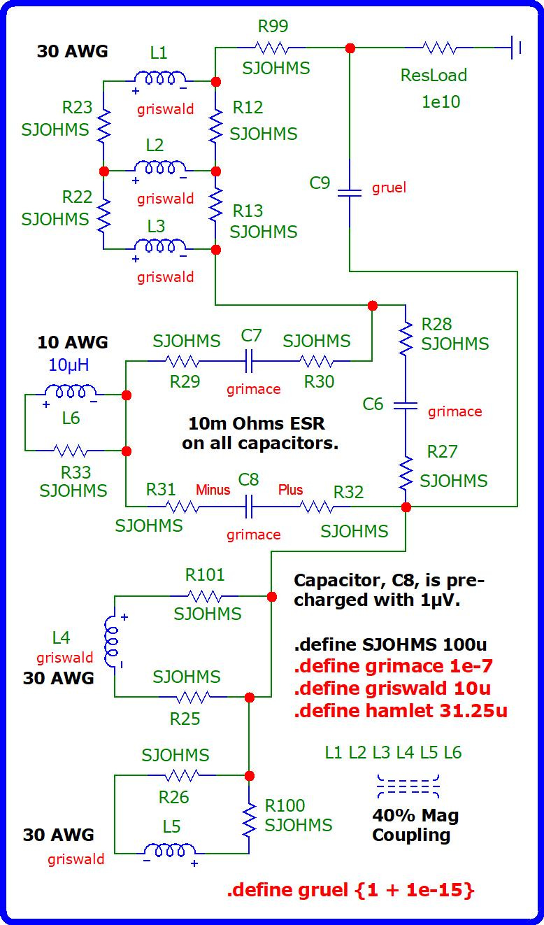
1e10 ohms of resistance is merely a limit, an upper boundary, for the resistive load, ResLoad, in the upper right corner of the schematic beyond which I got error messages under simulation. I take error messages seriously because they may not be a quirk of the simulator. There is the possibility that they may be an indication of stress being imposed upon the circuit. These types of circuits are already stressful to their components. Hence, I don't want to add to their burden any more than I have to.
I arbitrarily chose a value of 10 Milli ohms of equivalent series resistance for all of the capacitors assuming that all of them are ceramic.
I guess estimated what the series resistance for each coil was based on copper wire tables that are readily available so as to derive the wire gauge for each coil in AWG.
I assumed a maximum of solder joint resistance of 100 micro ohms.
I chose an inductance of 10 micro Henry's for each of the six coils.
I chose a capacitance for capacitors, C6 and C7 and C8, of 100 picofarads. Capacitor, C8, has the additional distinction of being pre-charged with the value of one microvolt to initiate putting the circuit into a condition of becoming ON. This is the only source of external power and, then, only momentarily available. These three capacitors form a triangular ring and are at the heart of the buildup of energy while all six coils are assisting them.
Capacitor, C9, functions differently in that its capacitance is anything greater than one farad to function as a storehouse to slow down the loss of power built up by the other three capacitors.
This circuit is intended to create a surge that will slowly dissipate after it reaches its peak. It is also expected that current will be drawn in from the ground through the resistive load to additionally slow down the entropic dissipation of power occurring throughout all of the components.
But, eventually, it is to be expected that this circuit will run down to a comatose condition of negligible or non-existent, ie. non-measurable, levels of power resident within the system.
This is not a sustainable system. But it does exemplify the principle of overunity lacking self-regulation, sustainability and practicality.
There is no voltage source, herein, to become drained of exorbitant levels of current to contribute to any confusion as to whether or not this system is over unity.
Hence, I assume that the grounding rod will guarantee a solid contact with the conductivity of the soil to serve as a supplemental source of current.
And any freely available current obtained from Earth ground cannot be considered a theft from anyone any more than drilling for oil and pumping oil out of the ground is a theft since the Earth provides natural gas and crude oil for free whenever it is available.
I don't know what the amp-hours are for the Earth. But I assume them to be larger than anything worth worrying about!
Nor am I concerned about contributing to the dirty electricity that all of our grounded appliances and grounded transmission lines already contribute to the Earth currents. I'll let somebody else worry about that since this is not intended to be a sustainable system. It is merely a proof of concept.
Revisiting Bewley's Archetype

A capacitor, C8, is precharged with 1μV providing the initial “kick” to get a transient surge started which peaks at approximately 4.786 million seconds with an averaged amplitude of -7.231e+59 volts…
🙏😎🌈🫣