


Modifying a Shorted Motor to Induce Overunity
{making use of an A/C single phase, induction motor as a source of inspiration}

A Schematic of a Shorted Motor which Lacks a Load -- audio excerpted from Jim Murray's Transforming Generator presentation.
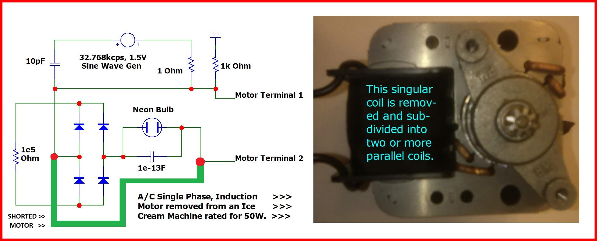
This is what I based my SPICE simulations upon was an A/C single phase, induction motor which I had removed from the Nostalgia (brand) Ice Cream Machine and attached an external, supportive circuit.
This schematic is what is referred to as a "shorted motor" as is noted by the thickened green connecting wire.
Steinmetz was hired by General Electric to back-engineer Westinghouse's (Tesla's) A/C patents to assist GE in its attempt to compete with Westinghouse. But prior to Steinmetz's success, anyone attempting to replicate Tesla's design would very often end up with a shorted motor of one type or another causing these motors to uncontrollably fry themselves.
Re: Can reactive power be recycled fast enough to power resistive loads?
« Reply #310 on: Today at 01:14:11 am »
Quote from: joeqsmith on Today at 12:17:29 am
I've learned from reading this thread and conversing with OP that SPICE doesn't actually treat that wire as one node. That's his backdoor connection point.
Yes, it does. It's node #5.
I've highlighted the motor short in yellow. The entire length of the wire which engages node #5 includes the yellow highlight in addition to a highlighted green wire which extends further than both ends of the yellow highlight in the attachment, below.
So, there are two shorts: the motor short and the sine source's short in addition to various parallel connections.
Re: Can reactive power be recycled fast enough to power resistive loads?
« Reply #313 on: Today at 01:46:28 am »
Quote from: SteveThackery on Yesterday at 11:01:35 pm
Quote from: Chet on Yesterday at 08:10:45 pm
A Schematic of a Shorted Motor which Lacks a Load -- audio excerpted from Jim Murray's Transforming Generator presentation.
{see attachment}
This schematic is what is referred to as a "shorted motor" as is noted by the thickened green connecting wire.
Steinmetz was hired by General Electric to back-engineer Westinghouse's (Tesla's) A/C patents to assist GE in its attempt to compete with Westinghouse. But prior to Steinmetz's success, anyone attempting to replicate Tesla's design would very often end up with a shorted motor of one type or another causing these motors to uncontrollably fry themselves.Chet, I've looked at the schematic and I don't understand it.
The only source of power is the 1.5V sine wave generator, which is shorted out. The neon will never light. The motor won't run even it weren't shorted out, because 1.5V isn't enough.
What is it supposed to do?
The input power is kept small so as to discourage its use as a source of power emanating from a prime mover located, and assumed, to be exterior to the circuit. Instead, this restricted input converts the sine voltage source into a catalyst which will make possible the injection of a 32k Hz frequency whose amplitude is of no immediate consequence. Yet, its beneficial consequence is delayed in as much as we have to wait for the accumulation of an over-reactive response to amount to a magnitude of notable quantity.
I have seen simulations which took tens of millions of seconds of simulator runtime to amass a useful quantity of magnitude, and nano-seconds, and immediately, and everything in between. But if I see a million-second slow growth rate, all I have to do is tweak the parameters and placements of various components to accelerate this process so as to get a result without having to wait so long.
Remember someone, here, mentioned how simulated extremes tend to produce anomalies contrary to conventional wisdom? (maybe you can remind me who said that and where in this thread?)
Well, that's exactly what I intentionally endeavor to produce that very anomaly whether or not it conforms to the concrete world of physicality, because that'll produce over-reactance among reactive components which I can take advantage of by accumulating that exponential response which starts out as a small response in the beginning — so small that it probably is not possible to measure it if it actually occurs in the concrete world of physicality. That's why “simulated extremes” may be a pertinent criticism, or it may merely be a pertinent parallelism — I'm not convinced, either way, which interpretation is correct in this specific instance. I'll have to wait and see what insight arises in my brain to address that relevant criticism.
So, 1.5V is intentionally not enough, because anything more than this would thwart my motives to let the accumulation of over-reactance make up the difference for powering this circuit with a potential source of negative watts.
Re: Can reactive power be recycled fast enough to power resistive loads?
« Reply #23 on: May 10, 2025, 07:45:06 pm »
Quote from: Someone on May 10, 2025, 01:07:20 am
Quote from: Chet on May 09, 2025, 11:48:29 pm
Quote from: TimFox on May 09, 2025, 10:57:00 pm
Voltage is not power. It is the energy in Joules per Coulomb of charge. In scientific and engineering usage, power is the rate of energy per time: 1 J/s = 1 W.
In popular natural language, there can be confusion between the words "strength", "force", "energy", "power", etc., but we are technical adults on this forum.
If you know that the load that you apply the voltage to is a pure resistance (obeying Ohm's Law), then you can calculate the power from the resistance and voltage.
If you know the current and voltage, you can calculate the instantaneous power and average it to get mean power.
Frequency can substitute for an inadequate voltage input especially if it is parasitic.
Please introduce to the world this
newconcept of parasitic frequency.
parasitic frequency — Bing search.
According to the link, above, parasitic oscillations are an unwanted by product of an unstable circuit. But I want it as a venture into "Controlled Chaos".
The slow development of a spiked, parasitic, elevated frequency modulating a slower sine wave — Web Archive.
The parasitic oscillation rides/forms piggy-back on top of its parent waveform. Yet, if the amplitude of this parasitic oscillation should happen to amplify its amplitude, then its parent waveform gets lost becoming an ever-shrinking parent in contrast to the amplitude of its child.
Re: Can reactive power be recycled fast enough to power resistive loads?
« Reply #72 on: May 14, 2025, 07:04:51 pm »
Quote from: paul cotter on May 13, 2025, 08:29:18 pm
Chet that is more nonsense, unfortunately. An LCR network is inherently lossy due to the resistance component and will always dissipate power.
As a friend (who was a staid businessman in charge of all of the rebar and concrete sold to contractors who built a four-leaf, clover leaf interchange on one of the freeways in downtown Los Angeles) once quipped, "money is only a problem to those who don't have it" in response to a question from a meditator as to whether or not wealth was a barrier to yoga practice.
Likewise, the dissipation of power, due to entropic losses and conversions, is only a problem if this rate of dissipation exceeds its replenishment.
But you've heard me say that already. So, I'm not saying anything new....yet.
Quote from: paul cotter on May 13, 2025, 08:29:18 pm
A low value of capacitance, how low due to want? You can easily make a cap of a couple of picofarads by twisting two pieces of narrow wire for a couple of turns and I have often done this for a light coupling at rf. You are correct that refractive index and dielectric constant are related but no capacitor is ever going to be a prism, it doesn't even make sense.
It'll never make sense in an LRC network. It'll make sense in an LRCC network. It takes two capacitors to actualize this phenomenon by the alteration of the dielectric field of each low-level capacitor by its partnered cap. This, then, becomes a parametric oscillation (see, below).
Quote from: paul cotter on May 13, 2025, 08:29:18 pm
There is a tiny amount of energy in the environment but unless you live near a transmission site you would be very lucky to barely light a sensitive led.
Only by using low levels of input power will the non-suppression of these effects occur. It doesn't have to come from the environment. But that's one example.
I found by experimentation/simulation that anything greater than 3V of a constant input was probably going to risk suppression of these overly reactive behaviors. And anything less than 1e-15V will also probably jeopardize a gainful outcome.
And even whenever I use 3V, I throw away most of it to ground/s using either voltage division or current division to diminish the input watts, because all I want out of the input is a frequency devoid of amplitude for the most part.
Quote from: paul cotter on May 13, 2025, 08:29:18 pm
A proper education in electrical engineering is not designed to maintain the status quo- it is designed to give you the basics so that subsequently you are only limited by your own imagination. To suggest that the system of education deliberately avoids areas of research that might challenge vested interests is conspiracy theory without **a shred of evidence**.
Good that I only need to provide a single shred! That saves me a lot of time looking all of them up!
Project Camelot interviews Ralph Ring, at 46 min. 18 sec.
Quote from: paul cotter on May 13, 2025, 08:29:18 pm
The current electrical theories work extremely well and need no improvement.
They need no improvement because if they got any better, then these theories would be too good for sustaining a robust economy.
That's not to say that our quality of life would go downhill if the economy were not robust since economy and quality of life are not necessarily codependent factors.
Quote from: paul cotter on May 13, 2025, 08:29:18 pm
The reason no research is done on free energy is because it is known to be a futile cul-de-sac. Chet ask Verpies or F6 about this and see what they say. PS: just noticed your query "theft". If you fool a utility meter into believing your power bill is less than it really is then that is theft.
None of my simulations do well whenever they are hooked up to the grid. So, I've almost exclusively focused my attention on providing power either from a sinusoidal voltage source which bleeds an excess of its power to ground, or else a capacitor which is precharged with 1e-6V more or less give or take several orders of magnitude in either direction.
I've watched the damping of the oscillation which results from the dissipation of precharged capacitances die out to values which are not measurable anymore followed several simulator-seconds later by an escalating oscillation which I can only view as being "parasitic" since the precharged energy has already disappeared from view.
Thus, ends my responses.
The attachments, below, are pertinent to the following post...
Ignorance vs Motivation
The trans-Atlantic telegraph transmission problem of the 1800s seemed like a daunting task. They couldn’t figure out, at first, why the messages were not getting through. It took the insights of Oliver Heaviside to figure it out.
The point is, that they didn’t give up. What with all of their failures, they wanted to be successful badly enough to keep at it even if a Mr. Whitehouse got fired for frying one of the cables of his company by assuming that all that’s needed is to give it more voltage.
You’re not taught about LRCC circuits because you’re taught to believe that anything more complicated than LRC can be converted into its equivalent version of an LRC.
But there is no equivalency for ignorance. To ignore the factor of variable parameters due to the significance of a variable dielectric field surrounding capacitors is equivalent to the trans-Atlantic telegraph transmission problem in which the engineers were ignoring something no one had ever taught them before: the magnetic leakage which was occurring all along the entire length of each and every transmission cable.
Why? Because their technological know-how was to assume that copper is good enough for the transmission of potential.
Yet, it wasn’t adequate for preventing magnetic leakage and the phase distortions which resulted between potential and current. For that, iron was needed along the entire length of the transmission line.
And it took Oliver Heaviside to suggest the additional use of iron for having seen it suggested in his mathematical simulations of (what has become known as) his Telegrapher’s Equations.
Parametric variations of the dielectric field surrounding each capacitor is more likely to occur with “unstable” parameters than it is likely to occur within the context of stable parameters. And a stable parameter is more likely to occur within an enlarged parameter than within a parameter so small that manufacturers don’t even sell them below one pico Farad.
That can’t stop anyone from “winging it” by fabricating their own variety of low-level capacitances by stringing a dozen or more pico Farad caps in series, but that has stopped anyone from assuming that it’s worth the bother, because electrical engineers are not taught the significance of parametric excitation.
There’s been some studies done on this topic – mostly to benefit audio engineering (see note #1, below), but not much emphasis is placed upon this topic within the realm of power stations.
It has been discovered that an amplification by a factor off two is possible. Simulators make the mistake of multiplying the amplitude of a signal by a factor of ten since they’re based on a decimal system of enumeration.
But the natural log base of ‘e’ is most likely the upper boundary of an exponential growth rate.
Still, that’s impressive!
Notes
BSTJ 15: 3. July 1936: Oscillations in an Electromechanical System. (Hussey, L.W.; Wrathall, L.R.) – “…When the impressed voltage was increased beyond a critical value mechanical vibrations suddenly built up and current of the difference frequency, larger in amplitude than the current of the impressed frequency, appeared in the electrical system.”
Klein Paradox – How an electron can pass through a barrier of electrostatic potential whose energy is greater than the energy of the electron by creating a pair of electrons one of which is the negation of its original making this inverse electron into the reversal of current. This describes the prismatic behavior of an extremely low-level of capacitance (significantly less than mere pico Farads).
Parametric Excitation of a Linear Oscillator, manual, by Eugene Butikov – “An important difference between parametric excitation and forced oscillations is related to the dependence of the growth of energy on the energy already stored in the system. While for forced excitation the increment of energy during one period is proportional to the amplitude of oscillations, i.e., to the square root of the energy, at parametric resonance the increment of energy is proportional to the energy stored in the system.” – Editor’s note: this latter condition of “the increment of energy is proportional to the energy stored in the system” makes it possible to witness exponential rates of growth of the amplitude of energy of a parametric oscillator. Although some of my simulations grow to infinity, others taper off at a plateau of amplitude to which the simulator treats this magnitude as if it were an unreachable limit. Butikov’s paper alludes to this: “In the case of parametric resonance, both the investment of energy caused by the modulation of a parameter and the frictional losses are proportional to the energy stored (to the square of the amplitude), and so their ratio does not depend on the amplitude. Therefore, parametric resonance is possible only when a threshold is exceeded, that is, when the increment of energy during a period (caused by the parametric variation) is larger than the amount of energy dissipated during the same time. To satisfy this requirement, the range of the parametric variation (the depth of modulation) must exceed some critical value. This critical (threshold) value of the modulation depth depends on friction. However, if the threshold is exceeded, the frictional losses of energy cannot restrict the growth of the amplitude. In a linear system the amplitude of parametrically excited oscillations must grow infinitely. In a nonlinear system the natural period depends on the amplitude of oscillations. If conditions for parametric resonance are fulfilled at small oscillations and the amplitude begins to grow, the conditions of resonance become violated at large amplitudes. In a real system the growth of the amplitude is restricted by nonlinear effects.”
Nonlinear Dynamics – “What is ‘nonlinear dynamics’? Isn't it a ridiculous term like ‘non-elephant zoology’?” – Editor’s note: seven years ago, I gathered together the pages of these links (notes #4, #5, and #6). But none of this registered with anything I had ever known about before then. Last summer was when I “woke up” to this concept. And, today, I get to rediscover my having saved these webpages onto my computer. So, unless you’ve already known about how pendulums can variously oscillate under these conditions of “non-elephant zoology”, it would not be surprising if you sweep it aside as another example of “word-salad” or something similarly useless or not relevant.
“The foldover effect got its name from the bending of the resonance peak in a[n] amplitude versus frequency plot…. That is, the nonlinear oscillator oscillates either with a large amplitude or a small amplitude.” – Editor’s note: either an exponential gain over time or a comatose state (far less than the input level of energy). Here is a plot of an exponential gain taken from this website… {see, below, in the attachments filename pendper - graphic used in my post.gif}
Parametrically excited oscillations – “In parametric resonance the amplitude of the unstable solution grows exponentially to infinity. Damping does not help to saturate this growth contrary to normal resonance caused by an additive driving force.”
Mr. Milkovic’s two-stage oscillator as a parametric oscillator, by Aleksandar B. Slavkovic, March 07, 2009
Gabriel's Horn, Wikipedia – “Gabriel's horn (also called Torricelli's trumpet) is a particular geometric figure that has infinite surface area but finite volume.” – I can relate the volume of this to the Conservation of Energy. Yet, the container of this, namely: electrical reactance, could be analogous to the surface area of Gabriel’s Horn. The significance is that our perception, i.e.: measurement, of the finite energetic content of an indefinite reactive containment can vary over time giving us equivalencies of the magnitude of content of an energetic system has also varied over time. These equivalencies are what we call parametric amplification. In other words, more work is performed per unit of energy of expenditure. A simulator can’t tell the difference. So, it renders its parametric results as an amplification of power. For all practical purposes, this constitutes a “quarterback end-run” around the limitation of a conserved quantity of energy without actually violating it.
Energy Harvesting using Parametric Excitation, by B. Zaghari.pdf (1063.96 kB - downloaded 4 times.)
how to pump a swing - power point.pdf (474.94 kB - downloaded 3 times.)
Klein Paradox - power point.pdf (965.19 kB - downloaded 4 times.)
Klein Paradox.pdf (538.44 kB - downloaded 3 times.)
oscillations in an electromechanical system, excerpt.jpg (110.37 kB, 883x658 - viewed 12 times.)
pendper - graphic used in my post.gif (3.45 kB, 293x274 - viewed 10 times.)
Re: Can reactive power be recycled fast enough to power resistive loads?
« Reply #92 on: May 15, 2025, 04:59:44 am »
Quote from: Analog Kid on May 15, 2025, 12:29:39 am
Quote from: Chet on May 15, 2025, 12:16:46 am
Quote from: Analog Kid on May 14, 2025, 11:42:01 pm
Please post a schematic, a sketch, anything concrete that we can use to see what exactly you're doing here.
Enough with the word salad. It's time for another course, hopefully a more nourishing one.See, post #83.
OK, now we're getting somewhere.
I'm taking the liberty of posting your schematic here for all to see:
(Attachment Link)
So now, would you care to explain in some detail how this is supposed to work?
"no-C2_10us_output_4-graphs.JPG" and "no-C2_20us_output_4-graphs.JPG" and "no-C2_50us_output_4-graphs.JPG" demonstrate in their upper two graphs that a parasitic oscillation has already begun to form within the resistor named, "Bulb100W" since they're oscillating faster than the sine wave generator's waveform in the lower two graphs. At "no-C2_100us_output_4-graphs.JPG", the amplitude of those parasitic oscillations appears to diminish, but picks up at "no-C2_200us_output_4-graphs.JPG" with an altered wave form of spikes which the simulator renders as triangle wave shapes but they're not since there are no plots other than the peaks and the troughs. The amplitude of these spikes becomes unstable at "no-C2_500us_output_4-graphs.JPG". This instability continues at "no-C2_1ms_output_4-graphs.JPG" with an additional feature of a more obvious growth of amplitude averaged over time. At "no-C2_2s_output_2-graphs.JPG", the output remains unstable but with a twist: it becomes a periodic instability peaking at a consistent limit due to a periodic collapse, after which, it quickly resumes its upward exponential growth rate from the bottom end of each collapse. This periodic collapse prevents an unbridled growth of amplitude.
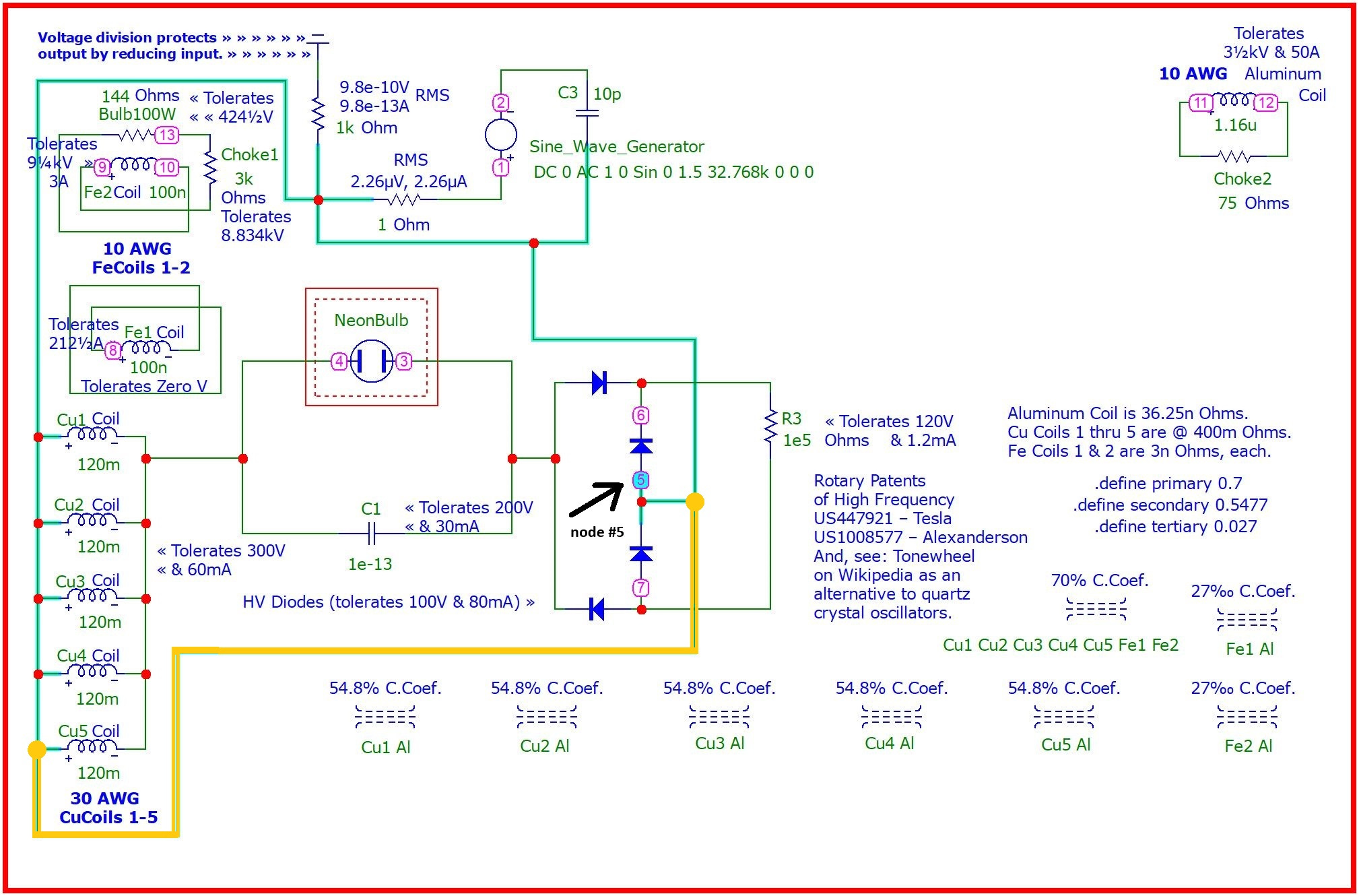
Yet, the peaks are a bit excessive since lightbulbs are not supposed to be capable of tolerating peaks of voltage at 424 and one-half volts. Yet, that's where the peaks of voltage top off at for the resistor which is named, "Bulb100W" in the upper left corner of the schematic. Since heat is the initial impetus for the filament of an incandescent lightbulb to become illuminated, these extreme peaks of voltage might be better suited for an electric heater after adjustments are made to accommodate the parameters of an electric heater?
Making these adjustments, although complicatedly involving several factors all at once, is possible which is what makes this circuit archetype one of my favorites (from a theoretical standpoint) if the mystery of how to build it could be resolved. I think there are four factors to simultaneously keep track of (if my memory serves me): the self-inductance parameters of each of the three sets of coils (counts as three parameters since each of the three sets of coils share the same value of self-inductance among each set), and the frequency of the sine source.
So, those claims of tolerance are not claims so much as they are requirements made upon those components.
The sine wave source is shorted to itself to reduce to a bare minimum its output so as to not interfere with my intention to nurture the formation of parasitic oscillations. For if these PO's don't form right away, then they won't form at all because they will become continuously suppressed. We can't see them on the ""no-C2_10us_output_4-graphs.JPG" graph. So, you'll have to trust me that they are there. It's like a fire you try to start by rubbing two sticks together in hopes of producing a spark to light some dry tinder nearby. The initial moments during simulator runtime are what make all the difference between success and failure.
I use the Trapezoidal approximation engine, rather than Gear or Backward Euler, since I don't have the patience to wait that long.
The inspiration for this design comes courtesy of a single-phase induction motor I removed from a Nostalgia Ice Cream Making Machine which runs its motor off of A/C at 50 watts. If you were to unwind the main coil of a single-phase induction motor and cut its magnetic winding wire into five equal lengths, and rewind them together in parallel connection to each other, then you'd have coils Cu1 through Cu5.
The starter coils for a single-phase induction motor have been renamed, Fe1 and Fe2. The aluminum coil in the upper right corner of the schematic represents the rotor coil of a single-phase induction motor.
The fact that these coils are named after copper, iron and aluminum is purely conjecture on my part in an attempt to speculate how to fashion three magnetic couplings among these eight coils in which three distinct and mathematically precise percentage of couplings are somehow made possible. This was my speculation when I drafted this schematic two years ago.
But now I'm of a different persuasion. I'm willing to speculate that ferrous and aluminum sheet metals might maneuver the magnetic couplings among these eight copper coils since Micro-Cap assumes that all stand-alone inductors will be wound with standard, copper enameled winding wire.
These three magnetic couplings are the byproduct of precise relationships of the following rules of thumb...
The first magnetic coupling between the five Cu1 through Cu5 coils and the two Fe1 and Fe2 coils, is defined by the ".define primary 0.7" statement in the middle of the schematic to the far right. It must be equal to or greater than the golden ratio of 61.8% and less than 100%.
The second magnetic coupling between the five Cu1 through Cu5 coils and the singular aluminum coil, is defined by the ".define secondary 0.5477" statement. This value results from subtracting the first coupling from 100% and taking its square root.
The third magnetic coupling between the two Fe1 and Fe2 coils and the lone aluminum coil is found by subtracting the first coupling from 100% and taking its cube power unless you chose for your first coupling the golden ratio in which case you take the fractional portion (to the right of the decimal point) of the square root of five to be this coupling. But if you were to choose 99% as your first coupling, then you'll probably have to adjust this third coupling up or down by trial and error or else remove this parameter from the simulation file since it will be extremely small: (1 - 0.99) = 0.01 when raised to the 3rd power = 0.000001 .
Just because this design was inspired by an electric ice cream machine motor does not imply that any of these coils are intended to rotate. Think of them, instead, as multiple coils interacting with each other in multiple ways. For instance, due to the lowered 3rd magnetic coupling, implies at least two things: a lowered mutual induction and an elevated mutual capacitance among these three coils since mutual capacitance and mutual inductance are inversely related to each other.
Quote from: Analog Kid on May 15, 2025, 12:29:39 am
What's with the coils made of different material (copper, iron, aluminum): why does the material matter?
You repeatedly write "tolerates XXXV" on various components: what does that mean? are those the voltage ratings of those parts?
The only source of power I see is your sinewave generator; is that correct? no other power inputs?
The neon bulb could be considered as a "source" since it produces negative current due to its negative resistance.
I did an interesting experiment in Paul Falstad's simulator in which I placed a battery in series with a negative resistor and a capacitor. Lo, and behold, the current went backwards -- recharging the battery -- despite whatever voltage I put into the battery.
For comparison...
Resistor, R5, of 100,000 ohms (1e5) replaces capacitor, C2, which used to occupy that position. But due to a hazard of the circuit blowing up if there was *any* residual charge left remaining on C2 from prior runs, I had to remove it and make other adjustments to accommodate its removal while retaining the characteristic behavior of this circuit.
no-C2_10us_output_4-graphs.JPG (129.54 kB, 1335x523 - viewed 19 times.)
no-C2_20us_output_4-graphs.JPG (131.42 kB, 1335x523 - viewed 12 times.)
no-C2_50us_output_4-graphs.JPG (132.58 kB, 1335x523 - viewed 12 times.)
no-C2_100us_output_4-graphs.JPG (130.06 kB, 1335x523 - viewed 12 times.)
no-C2_200us_output_4-graphs.JPG (146.66 kB, 1335x523 - viewed 17 times.)
no-C2_500us_output_4-graphs.JPG (178.32 kB, 1335x523 - viewed 14 times.)
no-C2_1ms_output_4-graphs.JPG (196.22 kB, 1335x523 - viewed 16 times.)
no-C2_2s_output_2-graphs.JPG (174.05 kB, 1335x523 - viewed 14 times.)
Re: Can reactive power be recycled fast enough to power resistive loads?
« Reply #128 on: May 15, 2025, 10:42:04 pm »
Quote from: TimFox on May 15, 2025, 07:30:56 pm
Ignoring mass quantities of nonsense in this thread, I would like to point out an important feature of simulations.
I learned this back when PSpice still used a 5-1/4" floppy as an access control (accessed at the start of each simulation, go past the hole drilled in the disc, and then verify the error statement).
For linear circuits, the .AC analysis assumes linear or linearized models of all components, then solves the complex algebra for the circuit analysis and should give an accurate answer for small-signal analysis in the frequency domain.
For non-linear circuits, using .TRAN analysis in Spice (and its derivatives), the calculation proceeds in time by numerical integration, where the next step in time depends on the state of this step in time, to calculate the signals in the time domain.
I had problems with simple circuits combining RLC resonant circuits and diodes (in non-linear conditions), and a useful customer engineer at PSpice asked first if my circuit had "storage", referring to the LC resonances.
He pointed out that with a high-Q resonant circuit, the analysis parameters (see any guide to Spice) needed to be modified greatly from the default values, or the errors due to excessive time steps would propagate quickly to give absurd values.
If one has very high resonant frequencies in the component values, the time steps must be much, much shorter than the very short period of any resonant frequency.
I don't know what the resonant frequency of this circuit is, nor do I think that there is one since "resonance" implies impedance matching? Which this does not conform to.
Nonetheless, ...
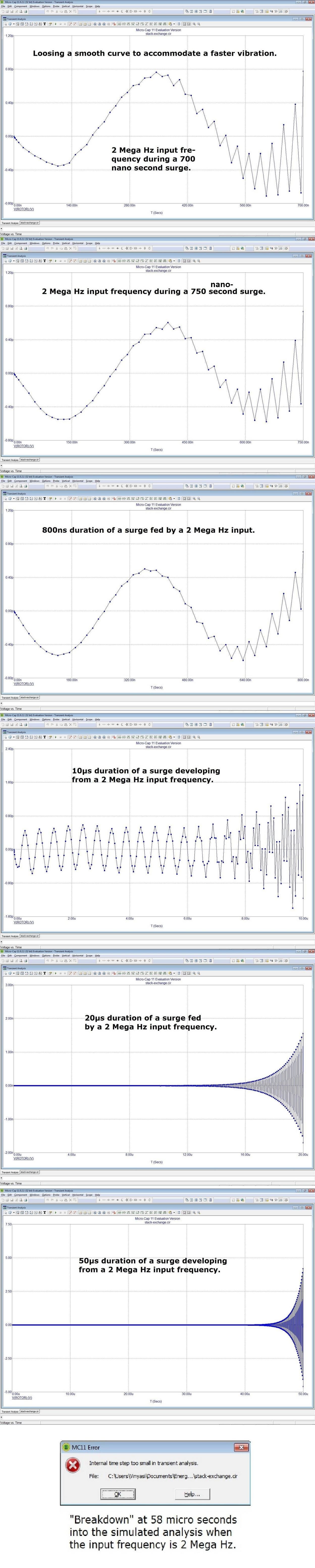
The multiplicative inverse (1/x) of 32,768 cps (x) of the sine input would imply that any maximum time interval less than 30us would suffice to destroy this anomaly if the sine wave generator had any say so in the matter which it doesn't since the input amplitude is so low and a parasitic frequency takes over with much higher amplitudes.
The frequency of the parasitic oscillation is 6us. So, if the maximum time interval is set for anything (significantly) less than 6us should prevent this anomalous circuit simulation from producing any "absurd" results?
Yet, that's not what happens! A smaller time interval injects a potential form of energy into the simulator's runtime causing an explosion of energy if this time interval is 20ns or less. Paul Falstad's simulator possesses the exact same shortcoming.
Please see my attached screenshots, below.
Great commentary!
This is why I keep the frequency of the sine wave input at its present setting since if I raise it too high, then this same type of explosive result will occur. But, if the input frequency is lowered too much, then a state of comatose levels of energy will result.
It's very difficult to create a condition (within any overunity simulation) of periodic collapsing of the tendency to exponentially rise to infinite gain. Comatose or explosive force is much more common. The commonality of a comatose condition is why everyone thinks that overunity is not possible.
Notice how I don't need to run the simulation for the same duration to achieve a minimum of two subsequent peaks of amplitude. I can reduce the runtime if I lower the maximum time interval. This is already indicating an increase of an injection of a potential form of energy well before the uncontrolled explosion takes place at a maximum time interval of 20ns or less.
20+us-max-time-step-duration-of-110ms.jpg (48.66 kB, 1353x541 - viewed 17 times.)
2us-max-time-step-duration-of-110ms.jpg (50.76 kB, 1353x541 - viewed 14 times.)
200ns-max-time-step-duration-of-1ms.jpg (48.05 kB, 1353x541 - viewed 14 times.)
20ns-or-less-max-time-step-duration-of-1ms-EXPLOSION.jpg (147.75 kB, 1366x768 - viewed 16 times.)
voltageOutputOfTheBulb100WResistorDuring250MilliSec.jpg (51.05 kB, 1353x541 - viewed 14 times.)
p2p-parasitic-frequency-v2.jpg (203.9 kB, 1366x768 - viewed 16 times.)
p2p-parasitic-frequency-v3.jpg (329.24 kB, 1366x768 - viewed 19 times.)
Quote from: joeqsmith on May 15, 2025, 10:43:01 pm
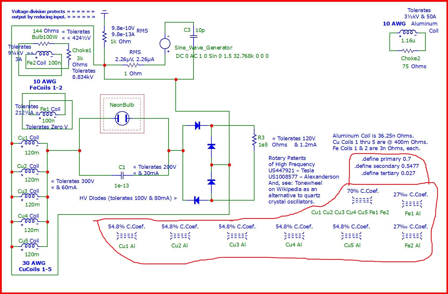
The generator loop is in its own self contained world with no defined way to couple with the outside, much like yourself. Or, I have completely missed this magical coupling mechanism. If I am wrong, please explain. You only have the generator, C and R in that loop.
Yes, you've overlooked the magnetic couplings which I've encircled in red in the attachment, below.
I’m going to have to cease attempting to keep up with replicating my postings over at EEVBlog Forum since it’s a lot of work merely keeping up with all of their comments and questions. But, here’s a compressed ZIP file of those postings stored on my Google drive.