


Nathan Stubblefield Technology
Or what we can salvage from what little we know of him.

The guys and gals over at EEV Blog Forum ( https://tinyurl.com/eevblog-reactance ) kept complaining about my lack of desire to build anything. From their point of view, I was not fulfilling the common sense dictum that it is the responsibility of the claimant to validate his/her claim of a theoretical premise by physically manifesting a device or a test procedure or whatever it takes to prove his/her claim.
For me, from my point of view, I would be a hypocrite (if I did what they demanded of me) since all of my simulations have been catered to satisfying our high-voltage, high-current, non-efficient appliances making my simulations not safe, nor user-friendly, due to the need of my simulations to exhibit extremely high nodal voltages.
These elevated nodal voltages make up for the lack of an external source of voltage driving current around within a circuit.
These elevated nodal voltages are very inefficient in contrast to making use of conventional, externalized sources of voltage, such as a battery or the utility grid, to push current around. Yet, elevated nodal voltages are cost effective since this type of overunity circuit merely requires an upfront cost at the time of its manufacture to pay for the elevated inductances and capacitances which are usually required to supply these elevated nodal voltages.
So, I’ve come to the conclusion that only the mild-voltage, low-current technology of Nathan Stubblefield would be safe for me to build.
But I have a problem. I tend to simulate electrical explosions despite my fervent desire to do the opposite! Oh, well…
https://tinyurl.com/nathansimple

So, I turned my attention to what little we know about his post-populist phase of the development of his technology. He continued to develop this technology after his failure to deliver his telluric telephony to New York city. This city, like any other city which engages in the use of an electrical transmission system, causes its underground environment to be filled with electro-smog. This prevented his successful demonstrations to attract and secure investors for his unique type of telephonic invention in that environment.
I have come to a few conclusions upon a recent re-examination of his system of energy generation…
He is applying Tesla’s “Radiant Apparatus…”, patent number US685957A.

Tesla's radiant energy patent contains a mast of elevated altitude upon which is located a rectangular sheet of metal touted as accumulating radiant energy from environmental sources such as the sun. This is a red herring intended to distract us from what an effective aerial – can be converted into – is a loading coil which is capable of accumulating energy from sources other than the sun and internal to the circuit to which it is attached.
Anybody who knows anything about radio transmission knows that you can shorten the length of your antenna (by effectively making it longer) by placing an inductor at its base inline with the antenna. You can see these types of aerials located on automobiles that have antennas that are quite short because, at the base of the antenna, the straight antenna turns into a curled helical coil before becoming attached to the surface of the motor vehicle.
So, ignore the mast and the sheet of metal at its top. And in parallel with the capacitor (down-below in his schematic), place another load which is going to be our loading coil to substitute for the aerial and the rectangular sheet of metal, up-above, that we no longer need to incorporate in our schematic version of what he had patented.
And let us double the number of loading coils and put them in magnetic coupling with each other to serve as a transformer in which one coil is made of insulated iron wire and the other coil is made of insulated copper wire to partly conform to the Earth Battery patent of Nathan Stubblefield.
The terminals of the iron coil will connect to an arc lantern whose spark gap requires 10,000 volts to ignite a spark between its electrodes.
A capacitor (which is depicted in Tesla's schematic) shorts out one terminal of the iron coil with one terminal of a copper coil and a resistive load is placed in series with this capacitor.
Both coils have the same number of turns within their windings exhibiting 250 Milli Henry's for the inductance of each of these two coils. And they are spaced apart in such a manner as to make their spacing variable so as to be able to adjust their mutual inductance in order to regulate the surge condition of this over-unity circuit to be able to turn it on and off at will.
When it is off and not surging, it will be depleting and losing energy due to entropy being the greater force taking place. This will occur when the two coils are moved apart slightly more than whatever distance is required to encourage over unity and a surge towards infinite gain.
So, this circuit requires constant supervision in as much as the surge condition cannot be allowed to maintain itself indefinitely without destroying the circuit. But when enough power gets built up within the entire circuit, then the surge is turned off by moving the coils slightly apart from each other (more than whatever distance they already possessed during surge mode) in order to encourage entropy to dominate over the tendency for this circuit to surge.
The capacitor that shorts out these two coils is also a bit peculiar because its capacitance is extremely low at a value of 10 to the power of negative 24 Farads of capacitance. Any greater capacitance than this will accelerate the surge condition when it is in surge mode making it difficult to regulate. Any lower capacitance than this is fine and dandy if you want to play it safe.
Let us include enough mass of iron winding and enough mass of iron core (around which both of these coils are wound) sufficient to possess a memory, of magnetic remanence, which is capable of sustaining (on average) sufficient amperage to constitute an equivalency of a consistent source of current which is capable of contributing to the condition of overunity that we seek to achieve in this circuit.
Voltage will dominate this circuit, without a whole lot of current in evidence, and this will satisfy the criteria of Nathan Stubblefield's implementation of Tesla's patent as being an electrostatic microgrid capable of generating a substantial quantity of potential powered by whatever power this circuit extracts from its environment.
Transcending the limitations of the formal education which is imparted to electrical engineers makes it possible for this type of circuit to generate the majority of its total power which is then added to the power coming into this circuit from an outside source.
The difference between the quantity of energy generated (within a circuit) and the quantity of energy entering from outside of the circuit, is the quantity of gain, also known as “over unity”, namely – a coefficient of performance greater than one.
This reshapes our definition of electrical reactance in which we have formally misrepresented this concept by calling it reactance as if it can only support conservation of energy without the capacity for any other option to be made available to ourselves.
Reactance is not the direct result of impedance intruding into the transmission of energy. Reactance is the indirect result of impedance serving as a stimulus to electrical reactance.
In other words, it is not necessary to have a magnetic field within which to move a coil in order to generate current within that coil. All that is needed is to displace the phase of current by one-half cycle of oscillation from its associated phase of voltage to constitute the generation of electrical energy from within reactive components.
There is nothing wrong with the Law of inductance discovered by Michael Faraday so long as we do not permit ourselves to be constricted to that law as if it's the only law of inductance in existence – because it is not!
Let us review the similarities and contrasts between Tesla's patent and Nathan's implementation of that patent by having a glimpse of my simulations in Paul Falstad's simulator.
https://tinyurl.com/fivethirdsrav4ev
https://tinyurl.com/7to1rav4ev
The only difference between these two links is the proportionality of voltage divided by current within a resistive load – which represents the inception of energy from the battery pack coming towards the motor controller of a Toyota RAV4 EV from 2002 – in which the 5/3 link represents full throttle acceleration at 206 amps versus 344 volts while the 7 to 1 link represents cruising speed on a level highway which only consumes 50 amps. Otherwise, these two simulations are exactly the same in their design and also in their operation.
Later on, I will add simulations within the context of Micro-Cap, version 12.
Tesla’s system utilizes an elevated mast to collect an adequate voltage difference between the top of his mast and ground. Nathan used an old oak tree for his mast. Since oak trees will be much shorter than a manmade mast (serving as an aerial) and his use of oak trees will probably lack any notable inductance (which a manmade, metallic aerial usually exhibits), Nathan increased the voltage difference of his “living” mast by inventing his “Earth Battery” which serves as a loading coil for his living aerial. This effectively elevated its height.
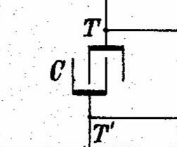
Despite Nathan's patent leading us astray by suggesting that his iron coil was made of bare wire, Nathan has made use of a transformer pair of loading coils, one of which is made of insulated iron wire and the other coil is made of insulated copper wire, in place of Tesla's capacitor labeled with the letter “C” in the diagram above.
Although I use a capacitor to store charge within my simulated speculation of Nathan Stubblefield’s electrical power station, I don't place it in the same location that Nikola Tesla places his capacitor (or “condenser” if you prefer the more correct term that he utilized) in parallel with his loads. Because, what's more significant, is the iron content of Nathan's loading coil (which he invented, and the U.S. Patent Office renamed an “Earth Battery”).
The insulated iron coil is the significant source of current which drives Nathan's power station because it is connected to his Arc Lantern at only one of the two terminals of the carbon electrodes of those lanterns. The other terminal is connected to the magnetizable iron chassis of the lantern causing the chassis to become a ground connection to the air leaking current into the atmosphere.
He hung these arc lanterns from the branches of the tree to which the loading coil was planted underneath its roots.
His usual habit was to plant this pair of loading coils beneath the roots of an old oak tree and wait a year before using it. This waiting period was probably required for a rise in voltage which slowly acquired an accumulation as a consequence of the coil’s iron content serving as a “current source”, namely: a source of constant current, whose voltage is allowed to vary to maintain a fixed level of current in defiance of whatever impedance and/or resistance should get in its way. The presence of iron, both in the iron core at the center of his coils, and within the iron windings laced throughout the windings of his copper loading coil, helped to “remember” the magnetic field of his copper loading coil.
Copper coils tend to forget their magnetism (due to their lack of remanence) which can especially be a problem over large distances as was discovered with the first installations of the low-voltage, trans-Atlantic, undersea, telegraph cables of the 1880s.
A minimum of approximately 250 milli Henry's of inductance is required on the iron loading coil (in the simulation, above) to develop enough voltage to overcome the resistance of the air gap within the arc lantern and light it up. And slightly more than 1μA is needed to fulfill this setup (a minimum of exactly 1μA plus 500pA (1.0005μA).
Most of the voltage that is required to drive this over unity circuit will accumulate within the capacitor which I have labeled on my schematic as Leyden jars.
Since some of this current manages to pass through his “living” oak tree serving as his mast, I asked AI (Gemini) over at Google to let me know how much leakage current is considered to be an acceptable tolerance. I wanted them to answer in terms of what I wanted to know, namely in terms of voltage divided by current. But they ignored this thinking I was asking the wrong question concerning resistance (since voltage divided by current equals resistance) which I was not asking. But whatever...
Although Gemini AI refused to satisfy my request, it did supply me with enough information so that I could interpret its answer in terms of what I wanted to know, namely: 10 microamps. Because, if I assume 120 volts at the outlet, and then divide by 10 microamps, then I get a ratio of 10 million to one (voltage divided by current) which is precisely what I had speculated and calculated in my head prior to asking the question! So, that’s a satisfactory answer from AI.
But I discovered that I could get away with using slightly more than 1 micro amp.