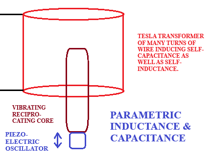
It’s so simple to theorize the design of a parametric coil which varies its inductance over time regulated by the frequency of an oscillator, such as: a piezoelectric, quartz crystal.
Imagine, if you will, a plunger — made of ferromagnetic material, such as: ferrite (for example) — is suspended within the central cavity of an air-cored coil of magnetic winding wire.
An optional bifilar winding could be the addition of an insulated iron wire to preserve, against leakage, the magnetic field of the copper-based coil.
This plunger is attached to the piezo-oscillator to vary the inductance of the coil over time.
It might be advantageous to pressurize whatever gaseous or liquid medium which fills the empty space surrounding these components within a dielectric vessel so as to increase the density of the surrounding medium and enlarge the duration and/or amplify the magnitude of its internal reflections of vibration?
This idea comes courtesy of Byron Brubaker based on Tesla’s patented method for constructing coils or capacitors under pressure. Byron has theorized these tubes may also have been pressurized during their operation as well as during their construction.
Maybe parametric excitation is the secret behind the mysterious design of Tesla’s twelve tubes which were alleged to be “radio tubes” by Peter Savo (or whichever other version of this story you subscribe to) of a 1930’s Pierce-Arrow demonstration in Buffalo, New York?
Here are some simulated examples (in LTSpice) of best-case scenarios of what to expect. These four ASC files were submitted by “Paco_” and downloaded from the shared folder of Google-Doc files at the Shawn Ryan Show website. I uploaded them to my shared folder of Google-Doc files and corrected them of minor (cosmetic) errors and added preformatted PLT extensioned files for displaying their outputs. ASC extensioned files are the simulation run-time files. »
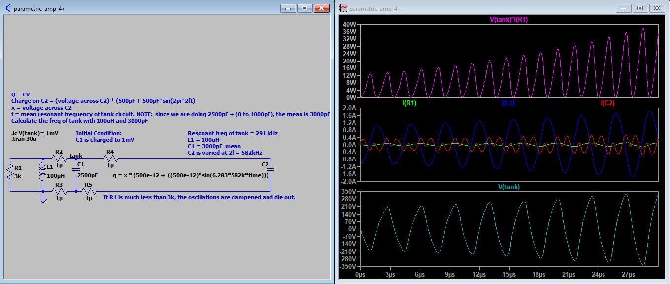
parametric-amp-4+
The capacitance of C2, on the far right, is oscillated as a sine wave times two times the resonant frequency of this tank circuit times the initial capacitance (of 500pF) plus this initial capacitance (to ensure a non-zero starting point for capacitance). And this is multiplied times whatever level of voltage is across capacitor, C2, at any given point in time. These calculations give the transitory capacitance, of C2, from one moment to the next.
This constitutes a parametric capacitance of a resonant tank circuit.
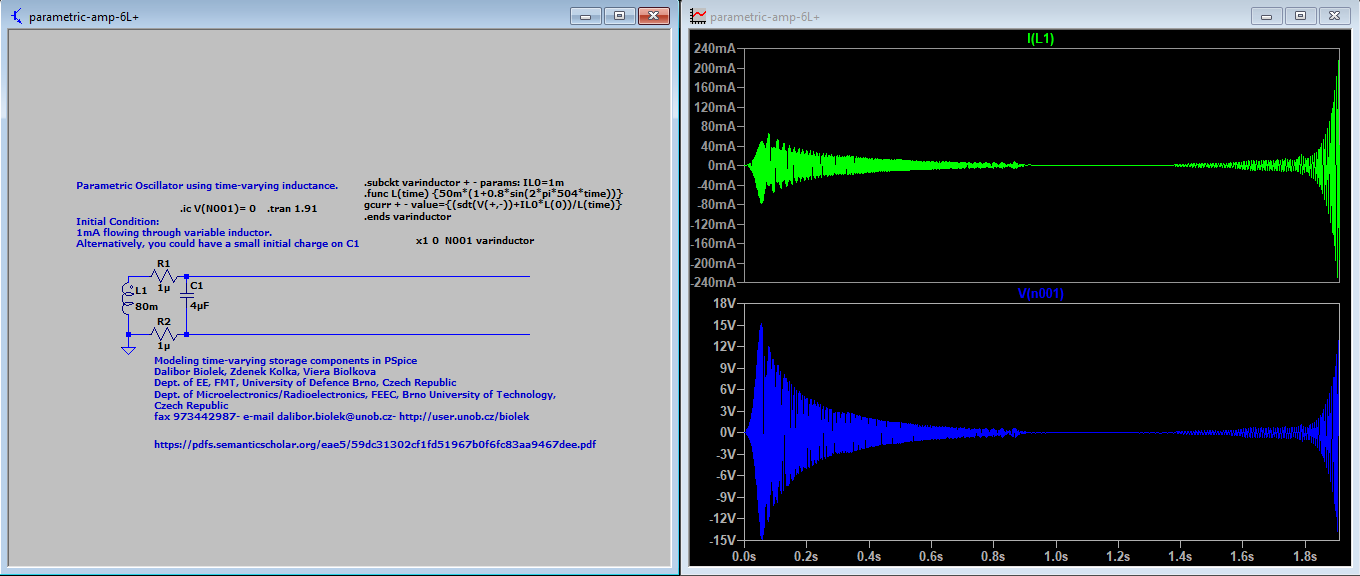
parametric-amp-6L+
In this scenario, the author (Paco) has placed a virtual inductor located above this schematic’s L1 in the wire which connects to L1 at its top end. The current of this virtual inductor (from moment to moment) is calculated based on its ephemeral existence — which does not actually exist except as a mathematical construct (as is stipulated on this schematic).
Just as voltage is mathematically presumed to increase with a decrease of capacitance (in the example, above), …
Parametric amplifiers also operate by changing a parameter of the amplifier. Intuitively, this can be understood as follows, for a variable capacitor-based amplifier. Charge Q in a capacitor obeys: Q=C×V. Therefore, the voltage across is:
… which is derived from:
Knowing the above, if a capacitor is charged until its voltage equals the sampled voltage of an incoming weak signal, and if the capacitor’s capacitance is then reduced (say, by manually moving the plates further apart), then the voltage across the capacitor will increase. In this way, the voltage of the weak signal is amplified.
So - likewise - is it assumed that current would increase with any increase of inductance taking place in the following example. »
You may also notice, in the simulation, above, that both the current and the voltage decrease, initially, due to entropy. Yet, they eventually begin to increase due to the influence of parasitic amplification which results from the parametric oscillations of virtual inductance.
This is what constitutes the usual source for the occurrence of parametric amplifications are the parasitic infestations which a non-stable circuit will encourage.
This type of engineering is not generally taught to students of this subject since their job description, when they graduate and get a job in this field, will demand that they do the opposite to what I do: they will entertain the notion of stability within a power supply or on a network of transmission lines.
Thus, engineers of today cannot possibly comprehend what I do much less how it is possible that I theoretically succeed. They just assume that modern day physics precludes “free energy”. This is because they can’t remember what engineers of over a century ago had to deal with were the commonplace occurrences of unstable networks which exploded in their collective faces. That has since been suppressed by the ingenuity of Charles Proteus Steinmetz. Engineers of today are not taught this, nor how conditions existed prior to his solutions, keeping modern day engineers ignorant of what I am seeking to revive with a twist: the controlled chaos of parasitic anomalies.
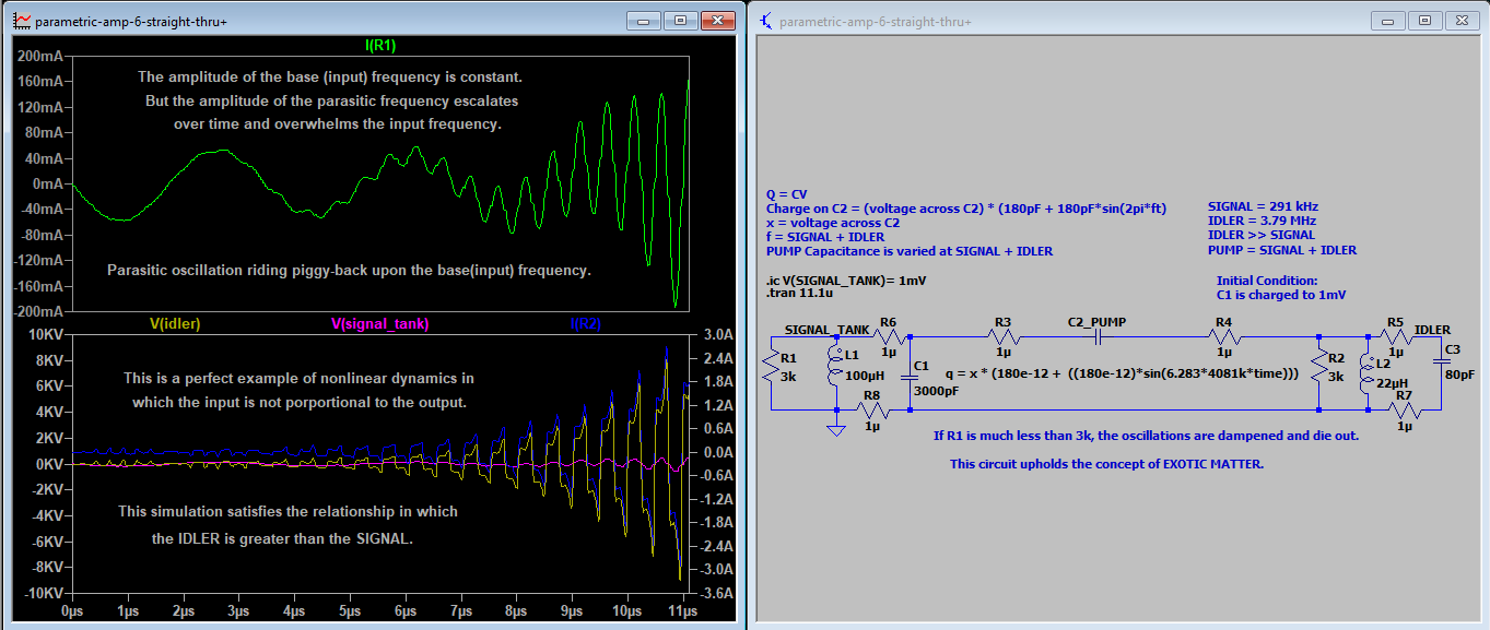
parametric-amp-6-straight-thru+
The power on the IDLER (right-hand side of the following schematic) is greater than the power of the SIGNAL (on the left-hand side).
It is plain to see that the current at the resistive load, on the left side (at R1) is composed of a parasitic oscillation riding piggy-back on top of the base sine wave frequency. The amplitude of this base frequency remains constant while the amplitude of the parasitic oscillation continuously escalates quickly overwhelming the base amplitude.
Since no one is willing to admit that power can come from nowhere, namely: from no physical location in space (since the imaginary field of numbers is not a physical phenomenon, nor is it provably existential), and because we have short attention spans when it comes to the history of the engineering profession, for these multiple reasons we tend to discredit this anomaly as being hocus-pocus.
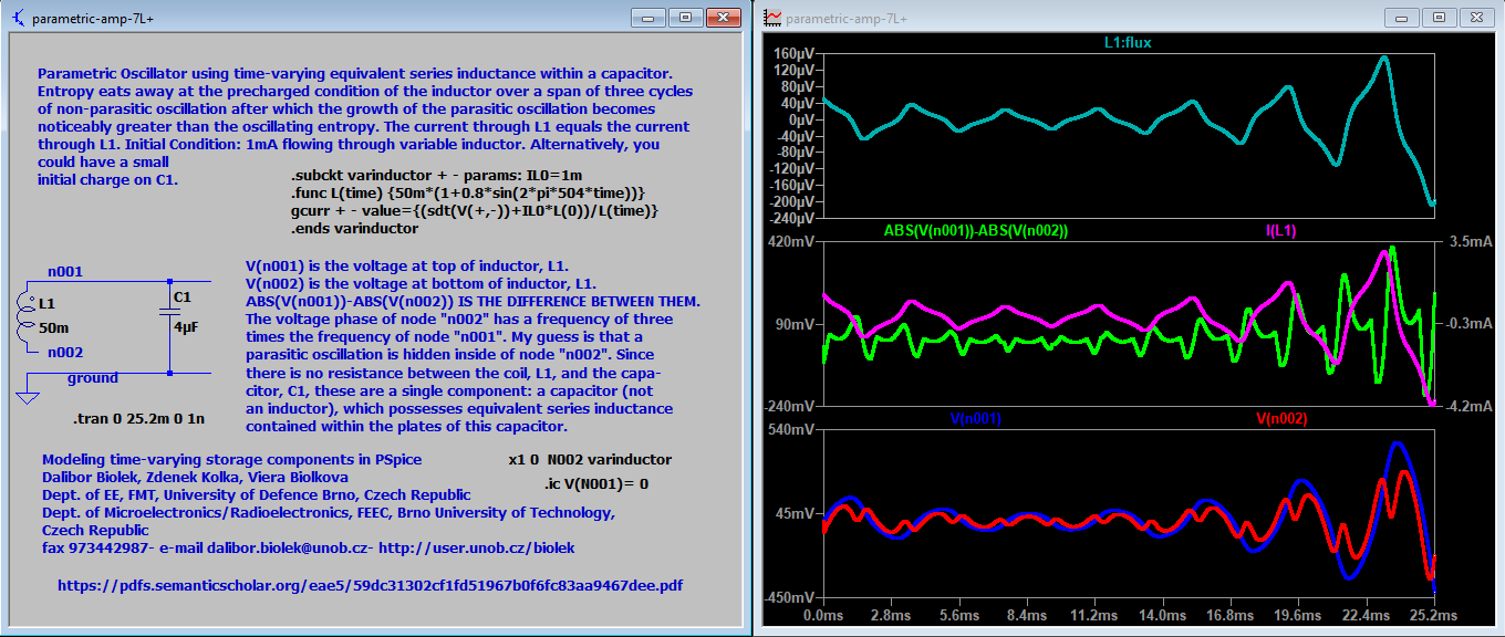
parametric-amp-7L+
My Conclusions
Most of my corrections are cosmetic (not fatal) errors involving the graphical format (arrangement) of the circuit’s components. But one correction was a fatal error: the filename of, parametric-amp-7L.asc. It required adding a restriction, during runtime, of limiting the size of its time steps to 1 nano second to eliminate errors up until the termination of runtime at 25.2 milli seconds. Any simulated duration longer than 25.6 milli seconds spawned a runtime error which would require lowering the time step (further) below its current limit of 1 nano second. It’s probably impossible to run this simulation for any indefinite duration without errors.
I did not significantly alter any of these circuits (which I’ve posted). But I did try putting a resistor between the inductor and the capacitor of parametric-amp-7L.asc which taught me that this is not a “realistic” simulation and all of the others are probably the same. They are probably not separate components. There is probably a union among some of them which significantly alters whatever conclusions we could possibly make.
USER BEWARE!
My version of LTSpice, which I am using for these simulations, is: (x64) 24.1.9 »
Here is Paco’s thematic reference for the creation of these simulations:
Modeling Time Varying Storage Components In Pspice
You may have noticed, by now, that the batteries are not a ‘source’ of energy for energizing this circuit. Rather, they are being used as ‘dampers’ to reduce the voltage which has a tendency of building up at various nodes in excess of need since these excessive nodes are far removed from the locations of the various loads.
This tends to happen a lot whenever I design an ‘overunity’ circuit simulation. So, if I want to be proficient and try to be professional about it, then I might make an attempt to reduce these nodal voltages somehow or another. This is one way to do it.
Voltage is needed to drive a circuit. But we don’t have to get it from an external source as commonsense would dictate. We can get it from within the circuit, itself, instead of from a battery, nor from the wall outlet, etc.
But the consequence of this novel way of thinking is that some section, or sections, of our circuit will become excessively endowed with voltage. Without killing the overunity of this type of circuit, it becomes a challenge to reduce its excesses.
INSTRUCTIONS FOR OPERATING THIS SIMULATION
Turn ON the simulation if it isn’t running already.
Hover your mouse cursor over the 2.2k Throttle (resistor) and roll the mouse wheel toward yourself to raise the parameter for this resistor up to a value of 2.7k and allow it to remain here for a little while to begin to light up the circuit. Careful! Don’t proceed with this step too far.
Reduce this resistor back down to 2.2k.
Close the switch which is labeled: ‘ENGAGE capL1’ and run this for a little while.
Open this switch and fiddle with the resistor UP or DOWN until you get capLoad2 and the resLOAD to where you want it (more or less).
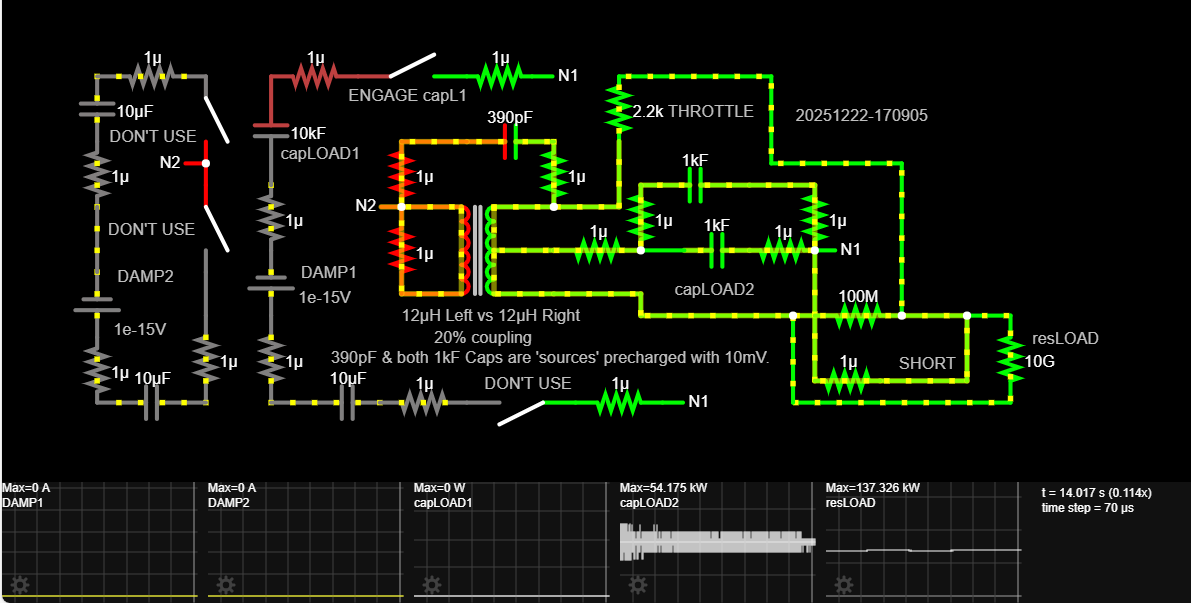
This simulation exhibits parametric excitation since the self-inductance of the transformer coil (on its left side is probably undergoing parametric transformation due to the magnetic fields surrounding its coils modifying each other’s currents.
This is analogous to moving a ferromagnetizable rod IN and OUT of the central cavity of one or more air-core coils — if they are all wound on the same bobbin (as exhibited in the graphic at the top of this post). This alters the self-inductance of the individual coils.
Thus, it stands to reason that modifying the flow of current on the right-side of this transformer (whenever toggling its various switches) will also modify its various self-inductances, because the alteration of the magnetic fields of the pair of coils (on the right-hand side) is substituting for a movable ferromagnetizable rod.
This is why I chose to use a transformer with a center tap, because I knew (by way of an intuitive hunch) that a toggle switch (on the tap-side) would drastically alter the magnetism of the right side and, thus, substitute for a movable iron plunger.
The left-hand transformer coil is the stable reference coil to serve as a counterpoint for the sudden parametric transformations of magnetism that will occur on the right-side every time any of the various switches are engaged (OPENED or CLOSED).
The capacitors are the sources of energy which initiates the running condition of this circuit simulation. The enormity of the enlarged resistances, and the variety of the capacitances, collectively ensure that overunity will result from the parametric alterations of self-inductance.
Although I claim that this simulation (within the context of Paul Falstad’s simulator) is “just for fun”, in reality, it actually is very instructive on how to conveniently go about engaging the principle of parametric amplification while using off-the-shelf parts.
I used to have a spark gap for the development of this simulation before learning that this circuit could run more efficiently if this spark gap were replaced with a capacitor in the range of pico Farads (390pF). This is why I prefer to simulate everything before even beginning to consider building anything, ‘cuz it’s so much easier to develop a concept which is extraordinary (outside of commonsense).
Most of us don’t have a clue how to translate an overunity circuit — which is simulated in Paul Falstad’s simulator — into a real-world build, because his simulator makes the trial-and-error development of overunity circuits so easy. There’s something odd about his simulator which remains a mystery to everyone including Paul!
Maybe this is how? » By immersing his simulator in a field of electrostatic charge?
In other words, maybe his “canvass” is one large block of a precharged electret? This would be analogous to the influence of a magnetic amplifier, or magamp. But, whereas a magamp injects a magnetic influence into one or more coils from outside of those coils (coming from another group of one or more coils or permanent magnets), in this instance, the injection is electrostatic — not magnetic.
I thought I was finished with the development of this last simulation (of a center-tapped transformer with switches and capacitors)! But I was wrong. I want to simulate it in other simulators, such as: LTSpice and Micro-Cap.