


Leave Nothing Untouched!
Delta–Star Formation of a Bewley Archetype.

This is a further development in which the delta-star connection between the primary and the secondary of a pole transformer (which isolates the customer from the electric utility grid) is utilized to express a slightly more convoluted version of the Bewley Archetype…
Here's what AI has to say about a delta-wye configuration on a pole transformer…
Delta-wye – what is it and why is it used on pole transformers?
A delta-wye transformer configuration uses a delta connection on the primary (high voltage) side and a wye (star) connection on the secondary (low voltage) side. This arrangement is common on pole transformers because the wye connection provides a neutral line, which is essential for supporting single-phase loads and improving system flexibility. The delta connection on the primary side helps isolate the secondary wye from the source and also helps handle unbalanced loads, according to Maddox Transformer. [1, 2, 3]
Here's a more detailed explanation:
Delta Connection:
In a delta configuration, the three phases of the transformer windings are connected in a loop (like a triangle). This connection does not have a neutral point. [1, 1, 4, 4, 5, 6, 7]
Wye Connection:
In a wye configuration, the three phases are connected to a common point (star) to create a neutral point. This neutral point provides a return path for single-phase loads, which are common in residential and commercial applications. [1, 1, 2, 2, 3, 3]
Why Delta-Wye on Pole Transformers?
Neutral for Single-Phase Loads: The wye connection on the secondary provides a neutral wire, allowing for single-phase power distribution (e.g., 120V). [1, 1, 2, 2]
Isolation: The delta connection on the primary isolates the secondary wye from the source, providing protection and preventing neutral currents from circulating back to the source. [1, 1]
Unbalanced Load Handling: The delta winding in a delta-wye transformer allows unbalanced neutral currents to circulate within the transformer itself, rather than flowing back to the source, according to Maddox Transformer. [1, 1, 8]
Harmonic Reduction: The delta winding provides a path for third-harmonic currents to circulate, which can help prevent distortion and improve power quality. [9, 9, 10, 11]
[1] https://www.maddox.com/resources/articles/delta-wye-connections
[2] https://shinenergy.net/how-delta-wye-transformer-improve-energy-efficiency/
[3] https://www.astrodynetdi.com/blog/3-phase-delta-vs-wye
[4] https://www.pumpsandsystems.com/why-wye-connection-why-delta-connection
[5] https://www.daelimtransformer.com/delta-wye-transformer.html
[6] https://tutco.com/conductive/making-sense-of-delta-wye
[8] https://www.linkedin.com/pulse/guide-delta-wye-transformer-connections-vmdqc
[9] https://en.wikipedia.org/wiki/Delta-wye_transformer
[10] https://www.daelimtransformer.com/delta-star-transformer.html
Please see the Higher Side Chats YouTube interview of Eric Dollard for his opinion of current events regarding this subject.
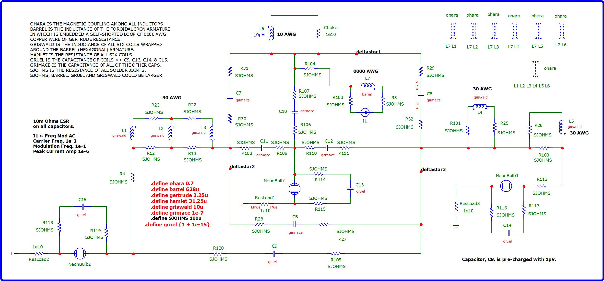
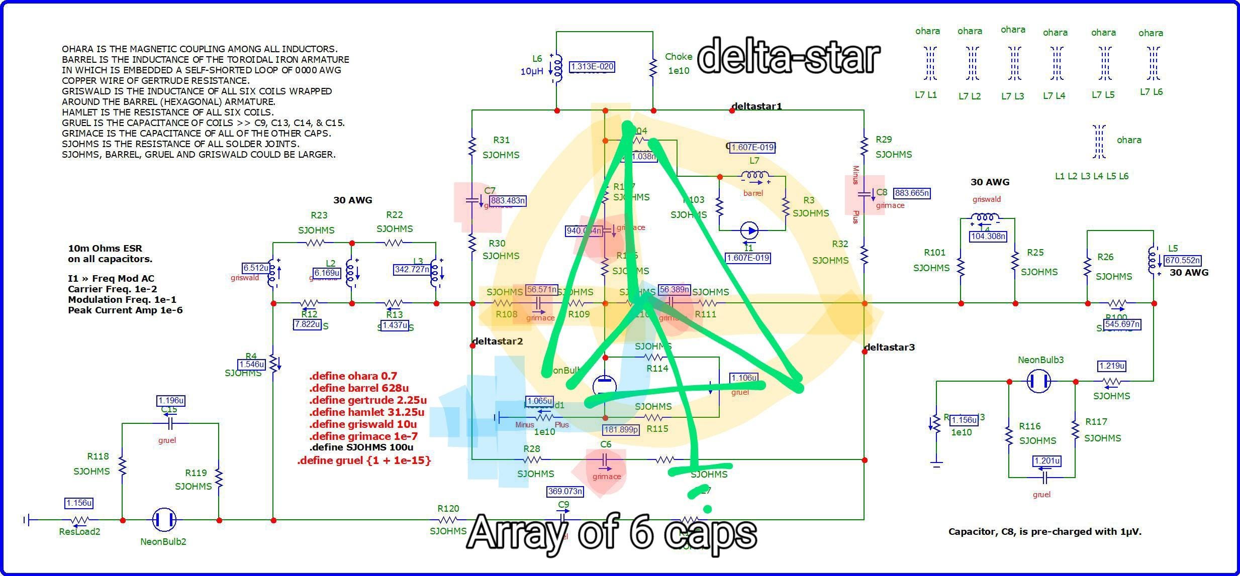
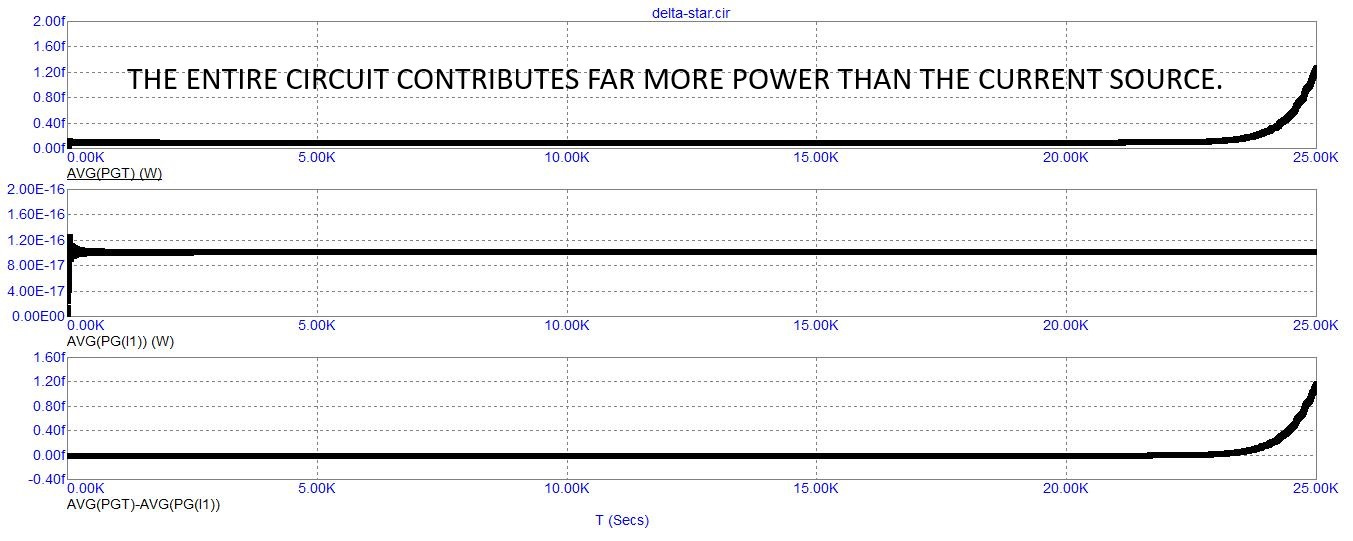
In this circuit simulation, I use a delta-star array of six capacitances at a low enough value of capacitance of 100 nano Farads to encourage the buildup of voltage among them.
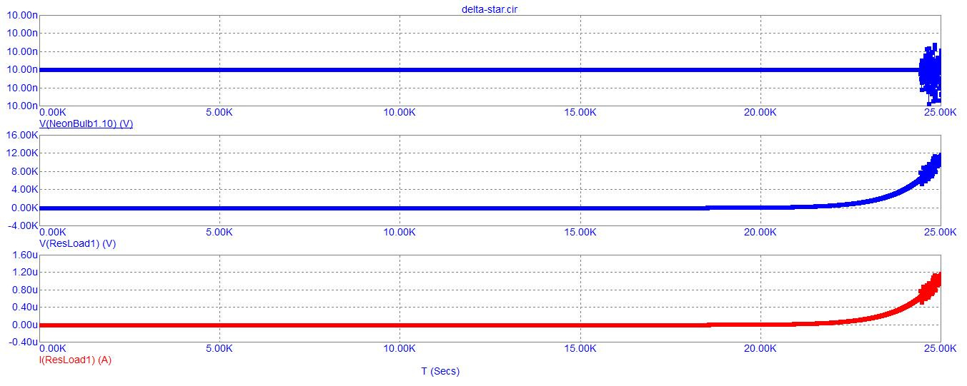
I connect the vertical axis of the inner star formation by a single wire connection to a self-looping copper wire of 0000 AWG embedded in the center of a hexagonal toroidal iron armature upon which is wound the six coils of 10 micro-Henrys. The circumference of the embedded copper loop is 30 cm which may not be enough to fit an armature around that heavy gauge wire in addition to wrapping a 10 micro-Henry coil on top of each hexagonal strut of the toroidal armature, but I took a guess without actually doing discrete calculations. It could be larger or it could be a smaller circumference to this armature and it's embedded copper loop the only difference being that the larger the circumference, then the more stable is the buildup of power and it takes slightly longer as well to reach the point in which the neon bulbs light up causing an additional injection of negative current into a situation which already contains a negative current buildup originating from the caps and coils.
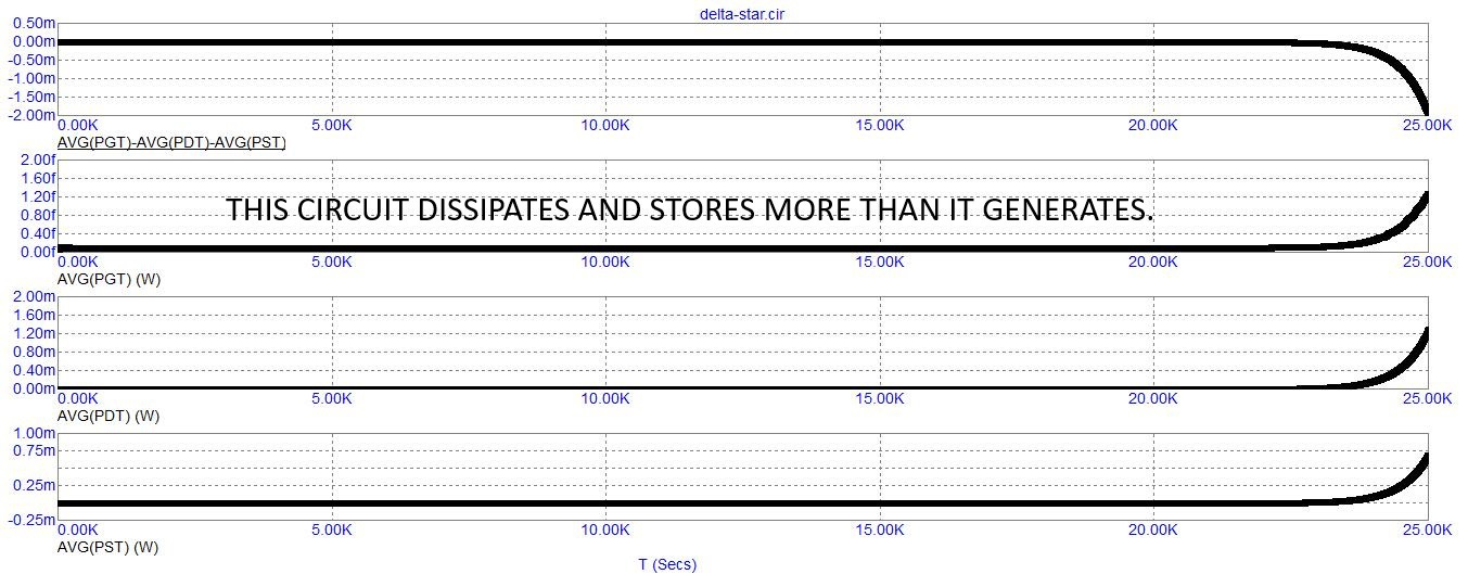
The inclusion of neon bulbs abruptly blows up the circuit rather than waiting a million or 10 million seconds for the buildup of power to slowly occur without the help of the neon bulbs. So, the buildup of power is predicated on the use of capacitances and inductances and resistances and the segregation of voltage buildup isolated from the maintenance of current. But this slow gradual buildup can be accelerated once the voltage breakdown occurs within neon bulbs located nearby to ground and a very large resistive load to hasten the explosive event.
Meanwhile, the maintenance of current more or less is kept segregated from the build-up of voltage by shorting out coils to themselves or in one case to a couple others and connecting the coils to the circuit by a single wire connection so that only voltage can transfer between the self-shorted coils and the other parts of the circuit. But that's an electrical consideration. Magnetically speaking, the coils are all connected to all the other coils which creates a pervasive interaction across the entire circuit without each coil making contact with the entire circuit via a double connection that would have encouraged the dissipation of current which I'm trying to prevent.
The only time I make a double connection between one or more coils, and the rest of the circuit, is to be able to pass that second connection through an enlarged capacitance (cap, C9) to help store voltage and maintain a semblance of stability to the growth of potential within the entire circuit.
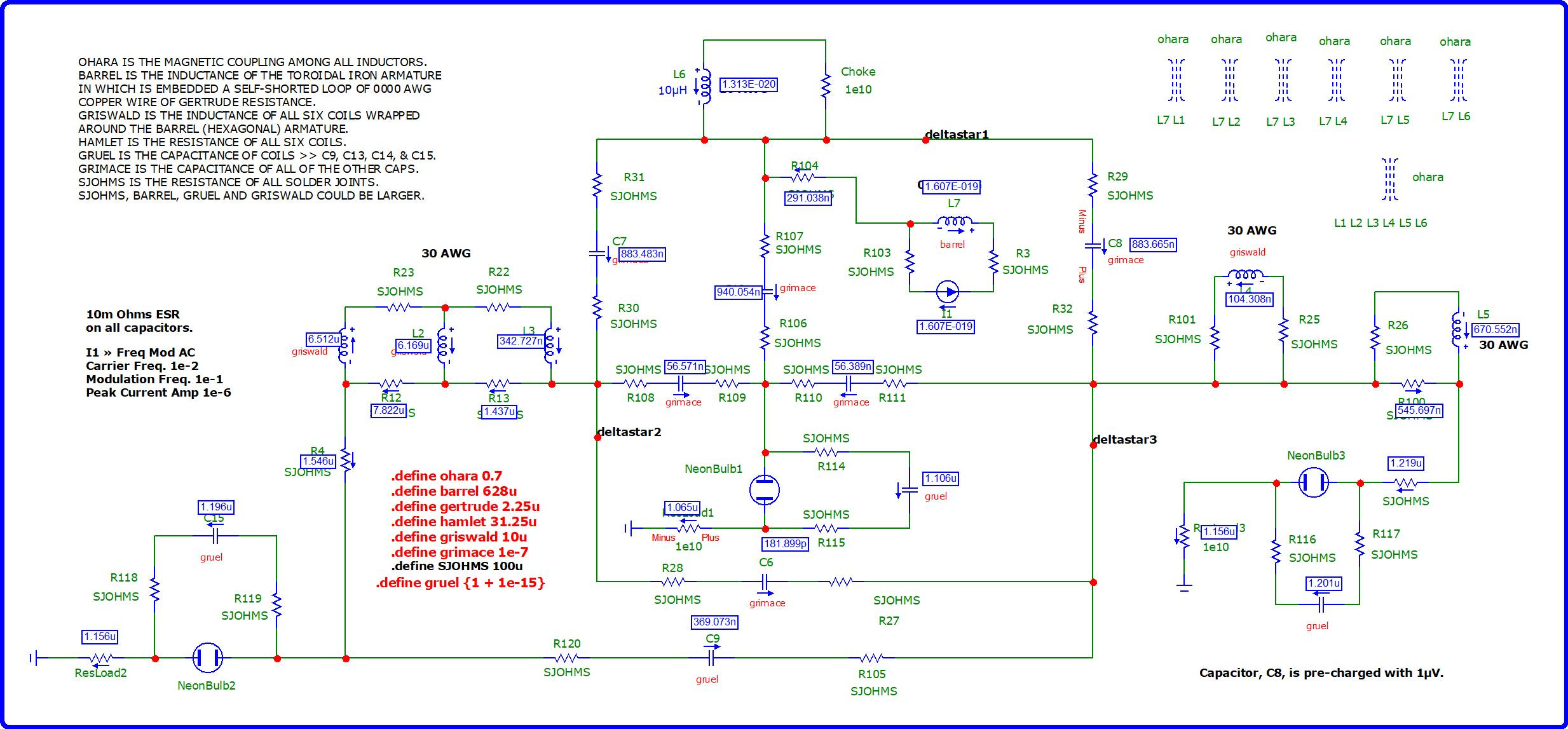
Here are some more screenshots…

Download a compressed ZIP file of all of the screenshots and the simulation files.
UPDATE
I’ve made some improvements shortening the duration prior to the “explosive event”, quickening the simulator’s response (at least, for a little while) before the simulator gets burdened with too many calculations resulting from a reduction of its choice of a time-interval (resulting from too rapid a change-of-state, ie. an explosion)…
Schematic…
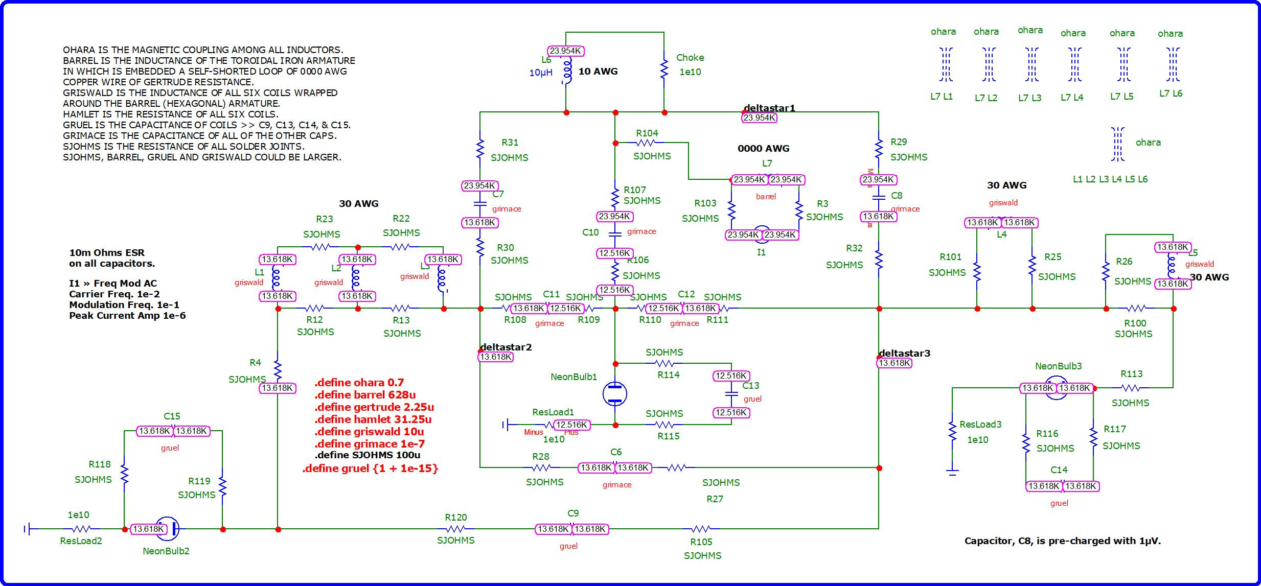
Nodal numbers, nodal voltages and currents all in one screenshot…
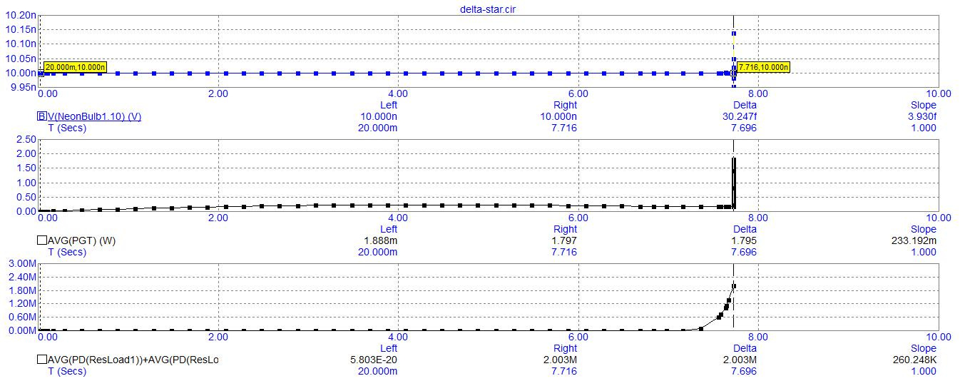
Graphical output which I terminate at around 7.716 seconds due to my boredom at waiting for some significant progress. Alas, there isn’t any at this point. But, at least the simulation does not produce any error messages…
Same graph as above, but with data points…
Download this circuit’s simulation file (extension “.cir” for use in Micro-Cap, v.12, 64-bit).
Download Micro-Cap, v.12…
https://archive.org/details/mc12cd_202110
Or here…
https://vinyasi.info/Micro-Cap_12/
(If you) build it, he will come...!

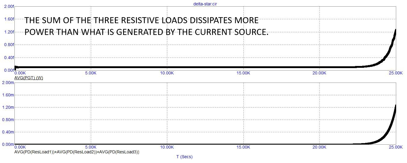
1e10 ohms of resistance is merely a limit, an upper boundary, for the resistive load, ResLoad, in the upper right corner of the schematic beyond which I got error messages under simulation. I take er…