


Sorry for the lack of a transcription of the audio file posted above. The system refuses to transcribe it.
Here is the recording of the short dialogue I had with AI on the topic of the radio broadcast of neon when ionized within a certain range of frequencies. 1 2
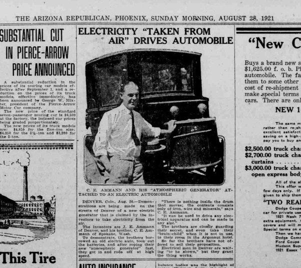
Here are a few screenshots of the source material at the foundation of the short dialogue I had with AI on the subject of neon when it ionizes does it put out a radio frequency? It does. Exactly as Byron Brubaker predicted to Joseph Newman and myself. All credit goes to Byron for this insight.


This vindicates Byron's suggestion to Joseph Newman on how to improve his device to make it over unity and it also gives us the foundation for understanding what an ideal transformer is. It is not simply something which does not dissipate energy. It is something more than that. It generates power to compensate for its losses in a manner analogous to Byron's suggestion to Joseph Newman back in the 1980s. 3
https://tinyurl.com/180microsecwavelength

In the podcast, I describe a two modality situation in which the simulated circuit, up above, can either build up in power or dissipate power.
Consequently, I have taken the liberty of positioning eight inductive loads within the interior of the circuit in the form of air-core coils of 2 micro henrys and 200 milli ohms of series resistance, each, as well as placing four similar inductive loads outside the circuit leading to ground to dissipate the energy buildup within the circuit during dissipation mode. This way, there will be four inductive loads located outside of the circuit during the dissipation of energy as well as eight inductive loads inside of the circuit during its build-up or its dissipation.
Paul Falstad's simulator contributes an input frequency in the form of its consistent time interval. This has to be taken into consideration and I assume it to be the radio frequency broadcast of a magnetic field during the ionization of whatever gas is inside of the dielectric canister wrapped with an open coil at the core of the ideal transformers depicted by Paul Falstad's simulator.
In my simulation, above, I chose a 180 microsecond time interval for Paul Falstad's simulator. This equates to a frequency of 5 and 1/2 kilohertz, approximately, of what could be neon gas inside of the dielectric canister acting as the core of his ideal transformers. Or else, this is some sort of mixture of noble gases since a Google search indicates that 15,000 kilohertz is the minimum frequency and 200,000 kilohertz is the maximum frequency of the electromagnetic broadcast of neon when it mildly glows short of full ionization (screenshots are located, above).
We can boil a car mug of water using a 50 watt, 4 inductive coil, heating element sized at 2 micro henrys, each, so this simulation (if built) can be minimally practical at boiling eight mugs of coffee or lighting up eight 25-watt light bulbs. 5 It demonstrates the essential idea that it is possible to run a set of minor loads off of an environmental value of voltage composed of no less than one micro volt suitable for powering a crystal radio from 100 years ago plus, of course, the reactive elements of the circuit using the principles of nonlinear dynamics in addition to thermodynamics.
There are only two important ingredients missing from the simulation, above.
The first important element that is missing is getting the noble gas inside of the dielectric canister (wound with an open coil) at the core of the circuit’s ideal transformers to ionize immediately at one micro volt. To do this will require shorting out the neon gas inside of the dielectric canister with some sort of conductive powder, such as graphene or gold dust.
The second important element which is missing is to prevent the circuit from compounding its power level to the point of destroying itself. Simulators don't have to worry about this, but we do when it comes time to build the simulation.
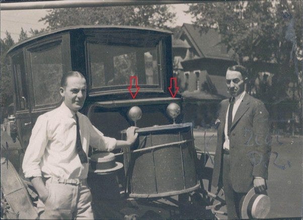
I believe that the Ammann brothers (in the photograph, above) solved this problem by surrounding their over unity circuit with a very large barrel-shaped coil made of bare iron wire the radius of which and the mass of iron utilized in that winding determines its ability to apply a magnetic braking effect to whatever circuit is within its interior to prevent that circuit from running out of control and frying itself.
The principal relevant to this situation is called remanence or the residual magnetism left behind in iron after the magnetic field applied to it is removed. 6
It is interesting to note that remanence is two-sided. Its standard and conventional definition is what's left behind in the iron after a magnetic field is removed. But the other way of looking at it is to consider the braking action that the iron has on a magnetic field surrounding it. Since this might be controversial, I asked this question on physics stack exchange for confirmation. 7
It turns out that iron wire from the hardware store is a soft magnetic material which can easily be magnetized and demagnetized according to Google's AI. 8
This braking action has direct impact on the magnetic field. But it also has an indirect impact on the electrostatic field which is what drives my overunity circuits in the first place is a parasitic oscillation driving up the amplitude of its voltage.
This is also called a perpetual motion holder experiment popularized by Edward Leedskalnin. 9
This is all very hypothetical on my part and so best of luck that you don't hurt yourself in the process of building this circuit.
🤔


Share this post