


Revisiting Bewley's Archetype
HINT... Without a Conventional "Source".

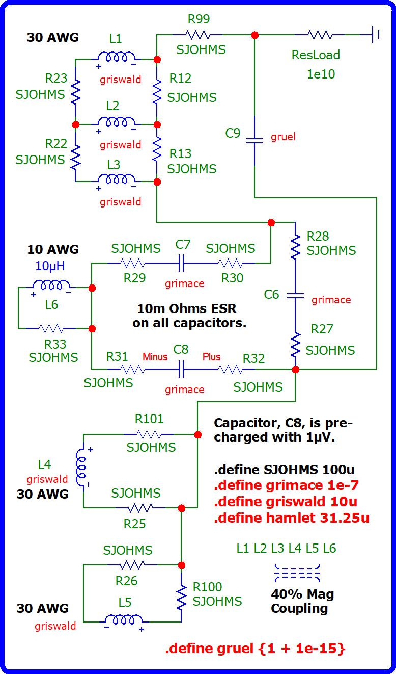
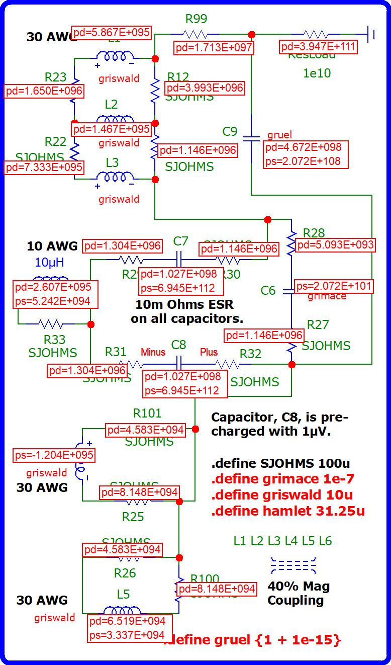
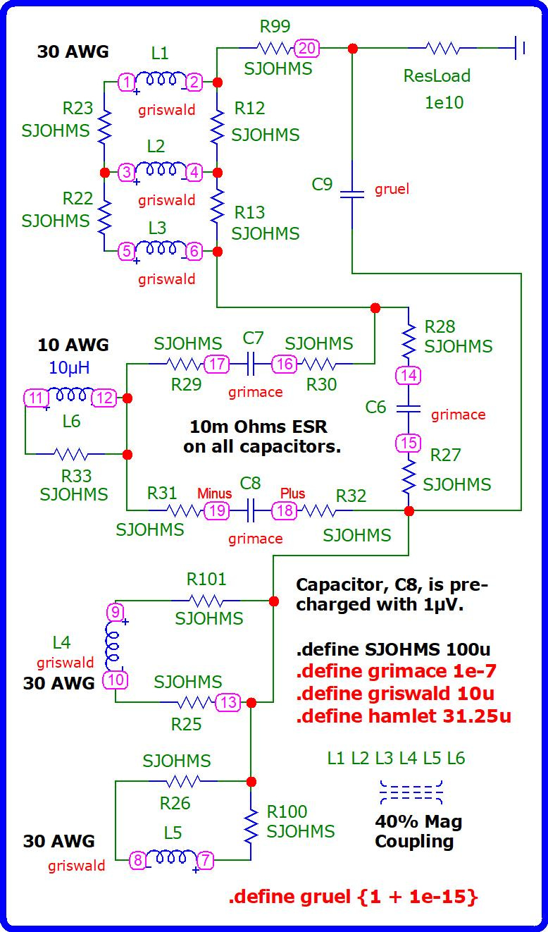
A capacitor, C8, is precharged with 1μV providing the initial “kick” to get a transient surge started which peaks at approximately 4.786 million seconds with an averaged amplitude of -7.231e+59 volts on the 1e+10Ω resistive load (ResLoad). It proceeds to dissipate its amplitude at a rate of approximately 90% per ten years.
A capacitor, C9, is added to help stabilize the storage of amplitude to mitigate the dissipation of power over time. Its minimum capacitance must be at least 1 femto Farad (1e-15F) above one Farad (1F) to prevent this simulation from rendering an error message.
All of the six coils are wound with magnetic, enameled copper, winding wire possessing 10 micro Henrys, each. Five of them are wound with 30 AWG gauge wire. The sixth coil is wound with 10 AWG gauge wire.
For the purposes of this simulation, I assumed that all of the capacitors were ceramic capacitors possessing 10 milliohms of equivalent series resistance, also known as ESR.
If you see a resistor whose value has a label signifying SJOHMS, that represents the preset value of the resistance of a solder joint.
I took a very conservative estimate guessing that the magnetic coupling among the six coils would be no better than 40%. But it may be higher when built.
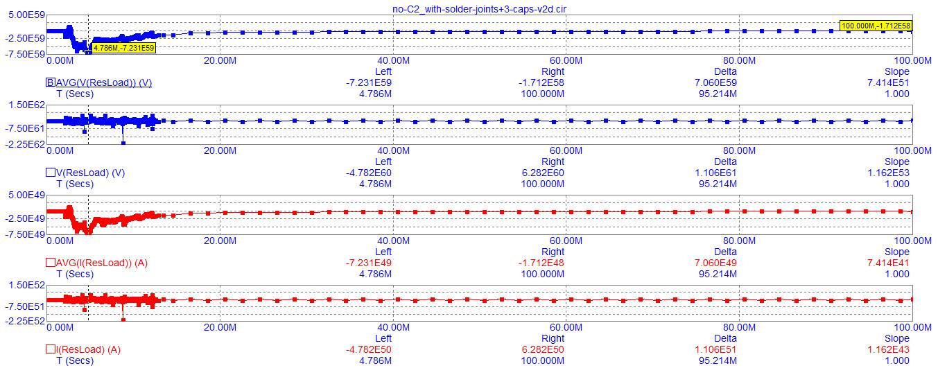
Output on a resistive load, ResLoad, possessing 1e+10 ohms of resistance…
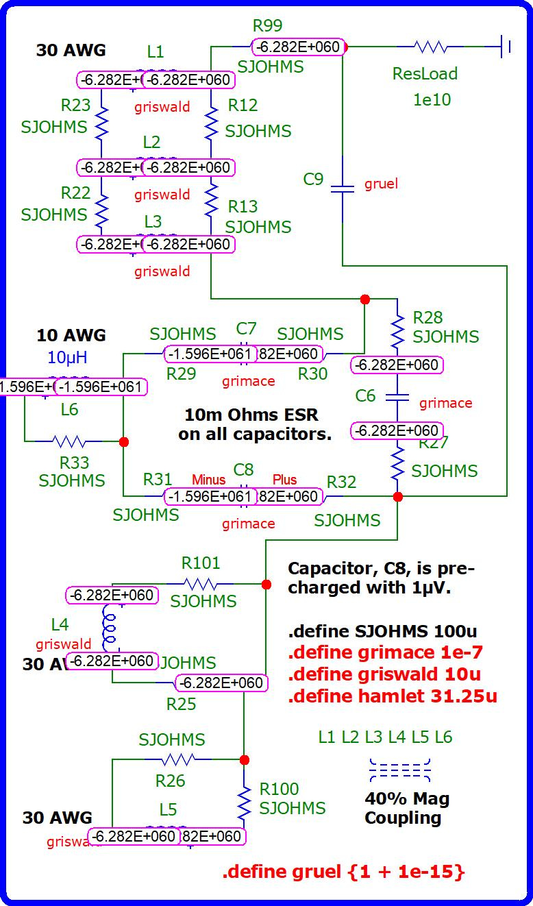
Nodal voltages after 100 million seconds of runtime…
Notice how the currents on the resistive load (in the upper-right corner of the following screenshot adjacent to the Earth ground) is coming into the circuit from the Earth and supplying the circuit with current? This is due to this circuit is acting like a heat pump, what I like to call a reactive pump, in which reactance pumps energy around against impedance, because these impedances have inverted the relationship that voltage normally has with current (in a conventional circuit).
Namely, instead of voltage pushing current, in this instance, voltage is sucking current into itself to amass more voltage to compensate the circuit for its losses as it dissipates energy through various components. This helps a lot because the circuit is dissipating power like crazy. So, pulling current in from the ground helps lessen the impact which entropy has on any circuit by putting off a comatose condition that will eventually result from the dissipative influence of entropy. In fact, this delay-of-dissipation slows down entropy to the extent that 90% of the power is not lost in this circuit until 10 years have passed.
The “load” (ResLoad) has become a “source”. Because of its proximity to ground, it possesses the largest value of current by comparison to all of the other components in the circuit. This so-called “load” supplies them with an ample amount of current and spends this current at the same time! What a concept!
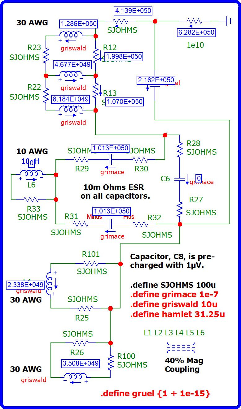
The dissipation and storage of powers (as measured in watts)…
Nodal numbers…
Copy and paste all of the text in the following PDF into a text editor, such as Windows Notepad, and save it with a “CIR” filename extension, such as: “simulated-circuit.cir”. Put quotation marks around your filename when you save it to guarantee the correct extension is added to this file rather than any other default extension.
Download Micro-Cap, v.12, to run this simulation…
https://archive.org/details/mc12cd_202110
Or, download Micro-Cap from here…
https://vinyasi.info/Micro-Cap_12/
First Epilogue
Reactance is the most difficult thing to regulate under conditions of extremely low voltage input. We don't usually have this problem, under conventional conditions, because we supply more than enough voltage (to our traditional circuits) in excess of their needs to cover not only their needs but also their losses. This excessive input of voltage more than adequately suppresses over-reactance and, thus, makes the regulation of reactance very easy. My job is very hard, because I have to come up with alternatives to the use of an excessive brute force of input voltage.
By the way, what we normally call negative impedance I prefer to call the inversion of voltage because that's the reality of the situation which we discover by observing our experiences and studying Watt's law in a different format from its conventional display, namely...
Instead of the overly simplified version of power equals voltage times current, we replace current with its equivalent expression of voltage divided by resistance and then we analyze the situation because it doesn't make any sense that voltage should be squared. It makes more sense to ask ourselves is there a difference between those two voltages that would cause them to be unique from each other so as not to be a squared condition of similar terms?
Yes, there is a difference. The first voltage is input voltage or the application of voltage to a component. The second voltage is its reaction to the application of voltage that initiated this reaction. And the so-called resistance that is dividing into this pair of voltages is not restricted to resistance, alone, but it also incorporates the impedances of capacitive impedance and inductive impedance. And all of this within a framework of time.
This is my way of delineating Watts law so that it's no longer Watt's law for it has become Joule's law if I may quote an expression which has yet to become commonplace.!
This is the true nature of negative impedance because if the values of voltage, both the input voltage and the resultant voltage, are imaginary values (square roots of negative numbers), then multiplying them against each other creates a negative voltage – a real value resultant. This is the true nature of negative Watts, AKA the generation of power, from within the circuit supplementing the scarce input of voltage from a prime mover if I should choose to starve the circuit of adequate voltage which of course I must do to get an over-reactance condition to occur.
Foster's reactance theorem allows for negative impedance but doesn't give a whole lot of information how to go about it! Well I just described it in a nutshell in the context of the expansion of Watt's law into something more articulate and precise because it includes everything instead of leaving so much out through its oversimplification.
The essential feature of Barbosa and Leal is the ability for their circuit to pull current from out of the ground in any quantity that one should desire utilizing the benefits of a circuit which overly reacts. This status turns conventional reactance into a pump of sorts very similar to the heat pumps that are utilized to move heat from solar collectors on the roof of a home into a reservoir of heated water underneath the home to be recirculated through radiators within the home during the evening.
Oddly enough, the simulator of Paul Falstad lists a ground component under the subtopic of “sources” probably because a ground is a voltage source of zero voltage.
Voltage sources, within the context of simulators, are considered to be fixed in their voltage. But they vary in their current to make up the difference. Should any impedance or resistance attempt to modify their voltage they, then, respond by maintaining their fixed level of voltage by altering their current. Hence, a voltage source of any value of voltage – from zero on up to Infinity – can supply an unlimited quantity of current under the right circumstances, namely: under the influence of the correct arrangement of capacitive impedances and inductive impedances and resistances. In other words, a zero voltage source (such as a ground) can become an unlimited source of current.
And more significantly then this, we don't have to limit ourselves to the concept of an unlimited source of direct current. But, we can also avail ourselves of an unlimited quantity of alternating current – which is far more useful, because it conserves wherever the current is coming from by reusing it (by taking current into our circuit and passing it back to the Earth, and then -again- taking the current from the Earth and bring it back to our circuit) for as long as we can keep this up. Because, all of the heat that our circuit will be dissipating will eventually go back to the Earth in one format or another unless any of it leaks out into space it's going to be recycled.
So, the only danger is not using up current as if it were a fixed medium, but using it up too quickly. And, so, we use an elevated frequency of a parasitic oscillation to increase our efficiency of current usage in contrast (or contradistinction) to direct current which is the least efficient method of utilizing current because you spend it once and it's gone.
But alternating current, of a sufficiently elevated frequency, provides an opportunity for the conservation of current by its reuse and all of this hedged against whatever rate of entropy is affecting our circuit so that we can come out of this competitive struggle with a net gain and overcome entropy.
Second Epilogue
Regarding — What is a transmission line in terms of Eric P. Dollard’s analogue assessment?
Re: Can reactive power be recycled fast enough to power resistive loads?

Ignoring the parameters of the following and paying attention merely to the arrangement of components...
https://tinyurl.com/temvslmd
This is some of what Eric derived from his study of LV Bewley. The triangular archetype of LV Bewley, which I derived from — and stumbled — upon quickly scanning the diagrams of Bewley’s published papers on the topic of traveling waves on transmission lines, is a simplified derivative of what can be achieved using Bewley as a starting point to inspire us.
Please refer to the previous post in this series for more information…
Bewley’s Archetype for a Transmission Network

Eric likes to point out that when he was a high school student (I think when he was 16), he pulled a book off the shelf of his electrical engineering father and read about transmission networks autho…