


Eric likes to point out that when he was a high school student (I think when he was 16), he pulled a book off the shelf of his electrical engineering father and read about transmission networks authored by L.V. Bewley. And the rest is history (as they say)…
Well, when I kept hearing Eric talk about L.V. Bewley, I thought, “Maybe I should look him up?” Sure enough, he's there on the internet for all to see…
Loyal V. Bewley – short biography.
L. V. Bewley, author details – I.E.E.E. Xplore
L. V. Bewley, “Traveling Waves on Transmission Systems,” in Transactions of the American Institute of Electrical Engineers, vol. 50, no. 2, pp. 532-550, June 1931, doi: 10.1109/T-AIEE.1931.5055827
keywords: {Lightning;Voltage control;Wiring;Optical reflection;Equivalent circuits;Propagation losses;Optical attenuators}
Bewley Archetype, a diagram of my derivation from L.V. Bewley's book.
Bewley Archetype, a proto-formation of my archetype in its initial stage of development.
Bewley Archetype, polished rendition, first version (second version, see diagram below).
“Traveling Waves on Transmission Systems,” a book, by L.V. Bewley.
“Traveling Waves on Transmission Systems,” his paper, by L.V. Bewley.
“Traveling Waves on Transmission Systems”, a PowerPoint presentation.
Traveling Waves on Transmission Networks – Scribd.
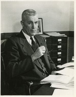
The following circuits are simulated in the virtual reality of Paul Falstad’s simulator. It is a mystery how to convert these simulations into a real-world build since his simulator is bizarre and so cool at the same time…
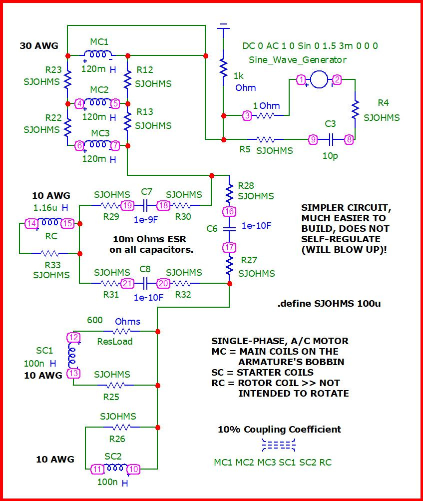
The following circuits embody the concept put forward by Eric Dollard of an analog computer in the modality of longitudinal magneto dielectric. Each module contains a pair of capacitors and a pair of coils on opposite sides of a four-sided module. Each module is electrically isolated from the next but magnetically coupled to each other.
The following simulations exemplify the Bewley archetype which is not much different than Eric Dollard's analog computer in LMD mode. This is why I got so turned on to the Bewley archetype and could appreciate Eric's concept.
Recharging a pair of 72V Batteries with 90V and 9A with 7 second Spikes.
Return Unlimited Current to the Grid w/one Caveat >>> it'll be riddled with SPIKES ! ! !
For comparison, we may contrast the four-legged archetype of L.V. Bewley, up above in Paul Falstad’s simulator, with a three-legged variety exemplified by the circuit, below…
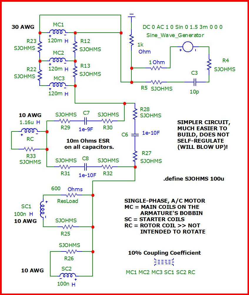
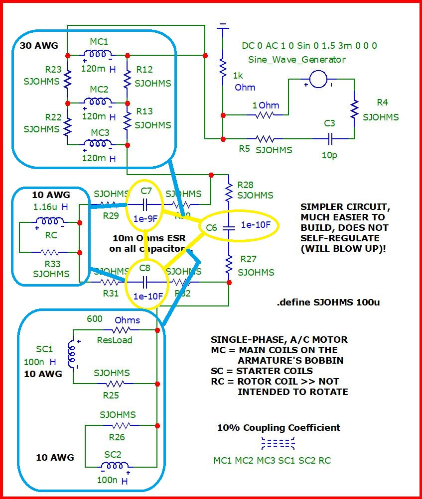
But regardless of the number of legs to this archetype, that I or you may derive from his work, at least two legs have to have one or more inductors in parallel with that capacitor in order to initiate an over-unity surge, also known as a transient surge – although in this case, it is anything but transient!
And in order to maintain this surge, so that it may not be merely a transient type of surge, every single capacitor (of the leg of this archetype) must have one or more inductors connected in parallel with that leg.
This archetype is not new. It is called: “ring capacitance”. {Hint — I made up this term since no one else has created a word which serves as a name for this archetype.}
And from this archetype, of L.V. Bewley, can be derived the analog computer of Eric Dollard in either transverse electromagnetic (TEM) modality or longitudinal magneto-dielectric (LMD) modality. Both types of analog computers (of Eric Dollard) are exemplified by the Bewley Archetype depending on which way the modules of this daisy chain are connected together to form a transmission line: TEM » Inductors in Series & Capacitors in Parallel (shunt) versus LMD » Inductors in Parallel & Capacitors in Series…
Transverse & Longitudinal Analog Networks – Eric P. Dollard
The schematic (again; a repetition from up-above)…
Nodal numbers…
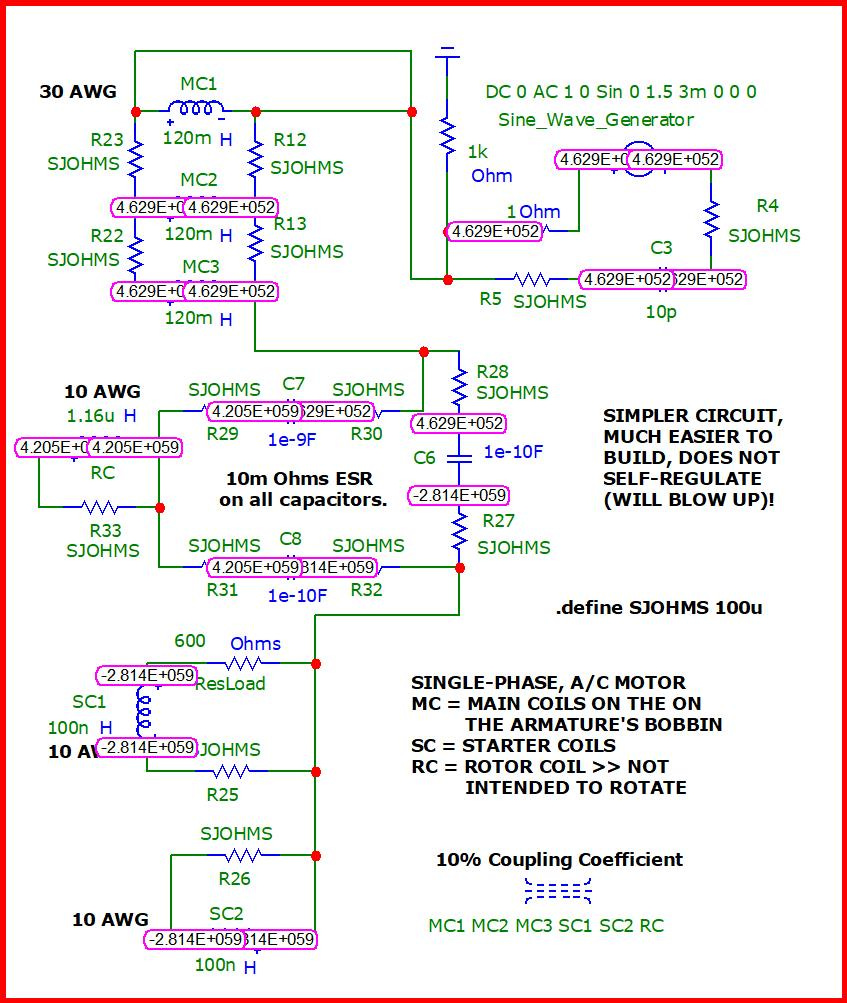
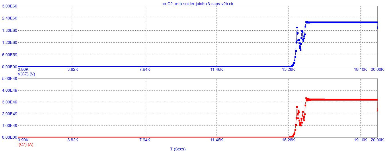
Nodal voltages acquired after 100 million seconds (3 years & 2 months & ¾ of a day) of simulator runtime…
Currents after 10 million seconds…
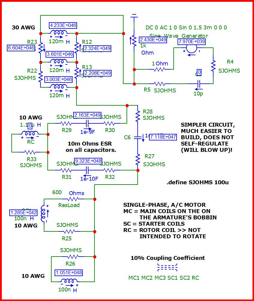
Currents become slightly elevated after 100 million seconds have transpired…

Towards the end of 100 million seconds of runtime, closeup…
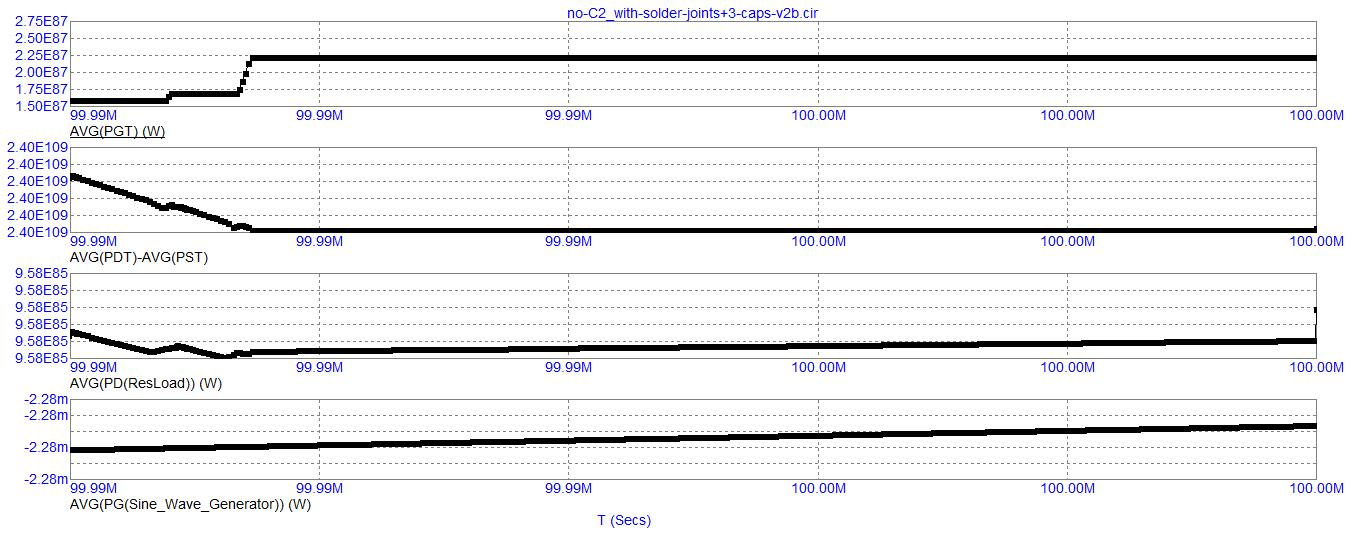
The following screenshot (of an 8 kilo second span of simulator runtime) captures the sine wave, voltage output of the sine wave generator and displays in the third graphic, down below, possessing a frequency of 333 & ⅓ spc (seconds per cycle)…
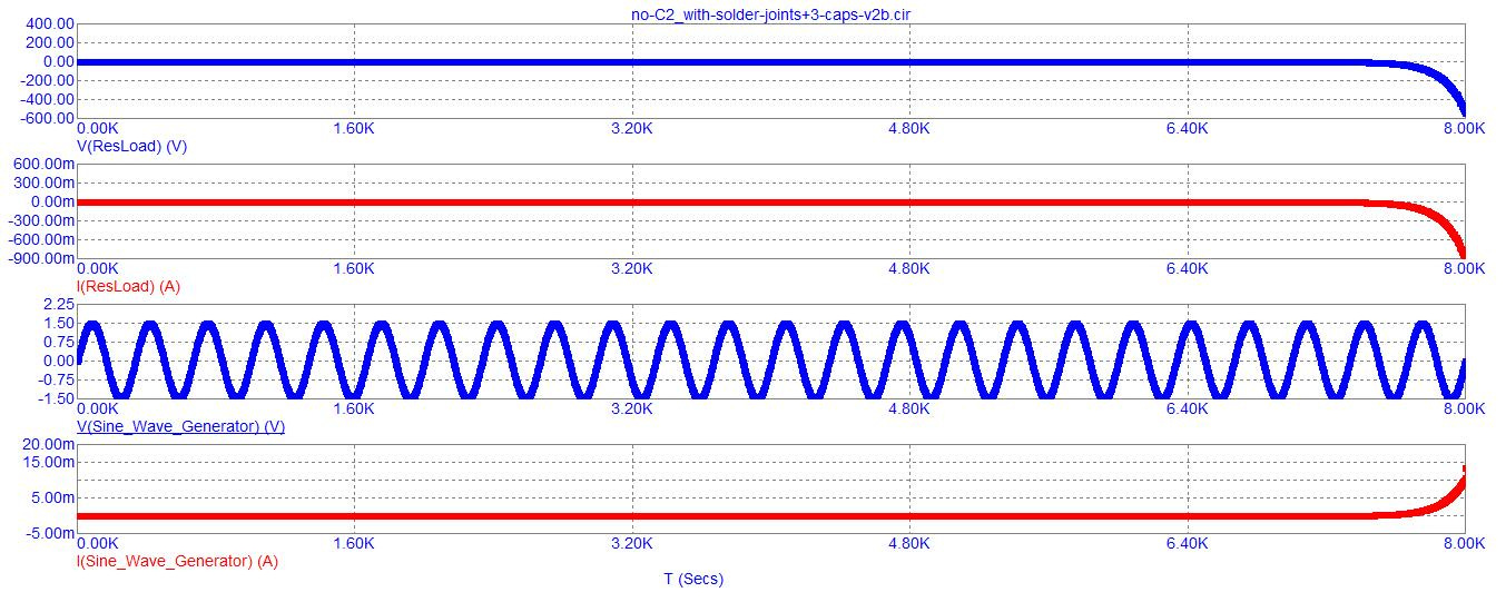
The inductors are necessary to store current in a conventional manner. Yet, this arrangement of capacitors in a circular ring is not conventional since it is unstable, but is necessary to drive up the voltage to whatever maximum amplitude the circuit is capable of delivering…

A PDF of the simulation’s coded instructions (which I copied from out of its “CIR” extensioned text-file) is here…
Select “all” of the text (in the PDF file, up above) and copy and paste it into a text editor, such as: Notepad or Word, etc, and save it in a text-only format with a “CIR” extension.
Download Micro-Cap, v.12…
https://archive.org/details/mc12cd_202110
And here…
https://vinyasi.info/Micro-Cap_12/
Warning!
I disagree with you (your expectation of me) that I might become a hero of sorts should I build it or anybody else build it and get successful results. Because the only results that will be successful is for the circuit to explode causing possible damage or harm to that person and his local vicinity in addition to the possibility for electrical harm spreading throughout that person's neighborhood through the power grid according to Eric Dollard.
Likely Harmful Major Changes Being Made to Power Grid per Eric Dollard


Share this post