


Stability and Instability within the Same Circuit!
In other words, how to generate and consume power at the same time and in the same circuit! What a concept!

If you want a lot of stability in a circuit that's going to be draining its stored power, it's conventional wisdom to make use of capacitances of a very high value such as super capacitors.
But if you want to create free energy, you have to do the opposite. You have to use capacitances that are so low that the capacitor in question is no longer functioning as a capacitor but is, instead, functioning as a prism due to the refractive index of prismatic material is the square root of the dielectric constant of dielectric materials (which are sandwiched in between the two plates of capacitors).
The Refraction of Current vs the Reflection of Voltage

I meandered around too much in the prior two podcasts when all I had to do was quote A.I., verbatim!
The Dielectric Constant versus the Refractive Index

The square root of the dielectric constant (κ) is equal to the refractive index (n) …
Resistance versus Reactance

In the following dialogue between myself and A.I. over at Bing Copilot, it takes a long time for me to realize that A.I. has made a mistake and in what manner has the mistake been made. But to its cr…
This poses a problem, because capacitors of such low parameters of capacitance can't store a charge, anymore, but have to function as a refractive prism, and cannot possess any degree of stability for discharging their stored voltage. No sooner than you drain them, the voltage is gone in an instant all due to the extremely low value of their capacitance. This is why super capacitors are so popular with the concept of stabilizing the drainage of a voltage charge.
But how do we get the benefits of extreme low capacitance and extreme high capacitance in a single circuit?
We accomplish this by connecting a pair of capacitors, one of extremely low value and one of extremely high value, in parallel with each other as in the following simulation…
The analog computer of Eric P. Dollard in longitudinal magneto-dielectric modality…
Transverse versus Longitudinal Electric Waves by Eric P. Dollard – a YouTube video.
…incorporating pairs of extremely different parallel capacitances positioned on the right side of the screenshots below.


When I initially set up this circuit-simulation, I was expecting to flip the switches because I was expecting to have to go into two different modes. One mode would be the accumulation of power while the other mode would be its expenditure through the heating coils of 10 Henrys and 100,000 ohms on the way to ground (located in the upper left-hand corner of the screenshots, above).
And I was expecting to switch capacitances between the two modalities utilizing the low-level capacitors for the buildup of power and the super capacitors for the dissipation of power. Thus, I put a transformer between each pair of capacitors to transfer the power from the low-level capacitor to the high level capacitor but keep them electrically isolated.
But, as fate would have it, Paul Falstad's simulator does not allow me to bother with separate modalities of the accumulation of power versus its expenditure. Instead, I found myself smack-dab in the middle of doing both at the same time! What a concept!! 😆
So, the circuit simulation builds up power and dissipates it through its load both at the same time while accumulating this storage of power all the way up to what the simulator considers to be its limit of amplitude and calls this limit “Infinity” for lack of some other vernacular.
And the simulation remains at Infinity and doesn't produce an error message – at least not within the limited duration of my experience with it. I did notice that it continues to elevate its amperage and so I don't know, if it errors or not, for certain.
And steering clear of “matrix is singular” error messages was a bit tricky. I had to be very precise in my magnetic coupling coefficient within the transformers that link each pair of capacitors to each other.
For comparison, here is the previous version of this circuit which requires two separate modalities functioning not at the same time…
First modality of the accumulation of power…

Second modality of its expenditure through an entropic inductive load…

You may notice that in these two screenshots the value of the capacitors have been altered from their low level to their high level while pausing the simulation using the stop button in the upper right hand corner.
I was expecting to use this cumbersome method because I'm no Chris Carson and I'm no Eric P. Dollard who can come up with a capacitor of high-speed rapidly alternating capacitances.
Adaptation to Circumstances
What can you do when you don't have super capacitors available?
No problem! We work with what you've got...
Let's assume all you have available are some milli farad capacitors you got off of Amazon.
We get the same beautiful results!...
https://tinyurl.com/switchedaclmdv2

Infinity, according to Paul Falstad's simulator, in 4 seconds! What a concept!
Aren't you glad we have simulators to give us hope for a better future? I sure am :-)

🙏
Analysis
When I first began to train myself on various simulators on how to create free energy – or I should say: how to expand the scarce energy that I provide the circuit into a humongous quantity of excessive power, I learned (early on) a couple of rules of thumb.
The first rule of thumb is to give the circuit so little energy that it could desire more, be driven and motivated to want more, if it had a consciousness to be tickled and teased – which I suspect a live circuit will undergo this experience and this consciousness even though we don't relegate any consciousness to a live circuit. Yet, we call it a live circuit! You would think we'd get it?
A second rule of thumb is to segregate and sequester the expansion of voltage into one area of the circuit and allocate another area of the circuit for the expansion of current – or the acquisition of current from somewhere else – driven by the voltage being amplified elsewhere in the circuit.
This is due to the fact that current and voltage are not the same phenomena. The voltage can be borrowed, and not spent, but will be necessary to drive the circuit. Meanwhile, the current will be spent and so we better get it from somewhere else lest we use it up and have no more to benefit from.
This is why it's very often beneficial to attach the circuit to ground. In fact, Paul Falstad's simulator puts the symbol for ground under the category of sources (such as voltage sources and other sources of energy), because that's what it is.
So long as we use voltage to extract current from the ground, we’ll be fine because: it's free current; free for the taking. But we won't be merely taking it, like in a direct current situation. We’ll be oscillating the current, alternating between taking the current out of the ground and putting it back into the ground, using alternating voltage to drive this action at a high-enough frequency that the rapid movement of current oscillating within our circuit will overcome entropy of the circuit and give us a net result of free energy.
This is merely one technique, but it's worth noting, because it's so simple (in its concept) in that we use voltage in a manner similar and analogous to heat pumps that are utilized to pump heat and move it from the solar panels on the roof of a home or building to the reservoir down below (underground) during the daytime and then of course reverse that action and move the warm water out of the reservoir and into radiators lining the interior spaces of the home in order to heat the home during the evening. The amount of energy utilized in order to do this is far less than the free energy we get from the sunshine.
Like this, we make use of voltage built-up within our free energy circuit, which by the way is very easy to build up (anybody can build up voltage), but we utilize this voltage to move current from places that are considered free sources. The ground is one example, but there are others, such as the imaginary plane of numbers known as the square roots of negative numbers also known as the Aether and also known as counter-space (this latter term comes to as courtesy of Eric P. Dollard; but I think he got it from someone else who lived nearly a century ago whose name I can't remember).
Anyway, to get back to the discussion,...
In the following screenshot I have drawn an arrow along 1/2 of this miniature loop, or closed subcircuit, in which current is allowed to pass because the two toggle switches at either end have ordained it to do so.

Meanwhile, the opposite side (above this in the diagram) there is no flow of current because the toggle switches are off for that pathway encouraging the buildup of voltage.
This is essential, because it is in the top-half of this small loop (these four small loops) in which voltage is going to be encouraged to increase due to the action of the extremely low capacitance of 20 nano farads while the bottom half is going to make use of that voltage transferred to it across the extremely low inductance of the transformer (within this small subcircuit) so as to store this voltage in the elevated capacitance (located on the bottom half of these four subcircuits) whose pathway of current is delineated by the orange arrow.
If you open up the edit window for these four transformers, you'll notice that their inductance is extremely low in the nano-henry range and their magnetic coupling is even more extremely lower than that to encourage mutual capacitance and discourage mutual inductance heightening the efficiency of the transfer of the voltage value of their electrostatic fields and diminishing the likelihood that any current will be transferred, because we don't want any current to transfer back from the bottom half of these subcircuits to the top of these four subcircuits.
Seeking a Way to Regulate (Throttle) the Outcome
Since the four transformers – which magnetically couple each pair of high and low value of capacitors – all possess a mutual inductance which is extremely low, it might be convenient to use this extreme spacing between the two coils of these transformers as a type of throttle to regulate whether or not the circuit is ON or OFF, and increasing its power or diminishing its power, just by moving these coils together to increase power or moving these coils apart to engage entropic decline of energy that's already in the circuit.
If only one of these four transformers is at 4% or above of mutual inductance, and if the circuit is designed to capture the transient surge which occurs at the beginning of runtime, then amplification of power will occur. But if all of these four transformers are at 3% of mutual inductance, then a very gradual decline will occur. Anything less than 3% of mutual inductance among all four transformers will be a more severe rate of decline of whatever energy has already been accumulated within the circuit.
This principle, of having a transient surge at the beginning of runtime and having a properly designed circuit to capture it and nurture it into any quantity of power desired over any duration of simulated runtime for this amplification to occur, is covered in the presentation I gave at a weekend conference among computer database engineers wherein I had already submitted and had been accepted for publication of my peer reviewed article into their database journal.
This may seem to be out of place for a treatment of electrical engineering under the topic of General Relativity, but it probably would never have been published any other way. So, I am lucky! 🍀
https://tinyurl.com/throttledaclmd
Turning the simulation on (clicking on the link, above)...
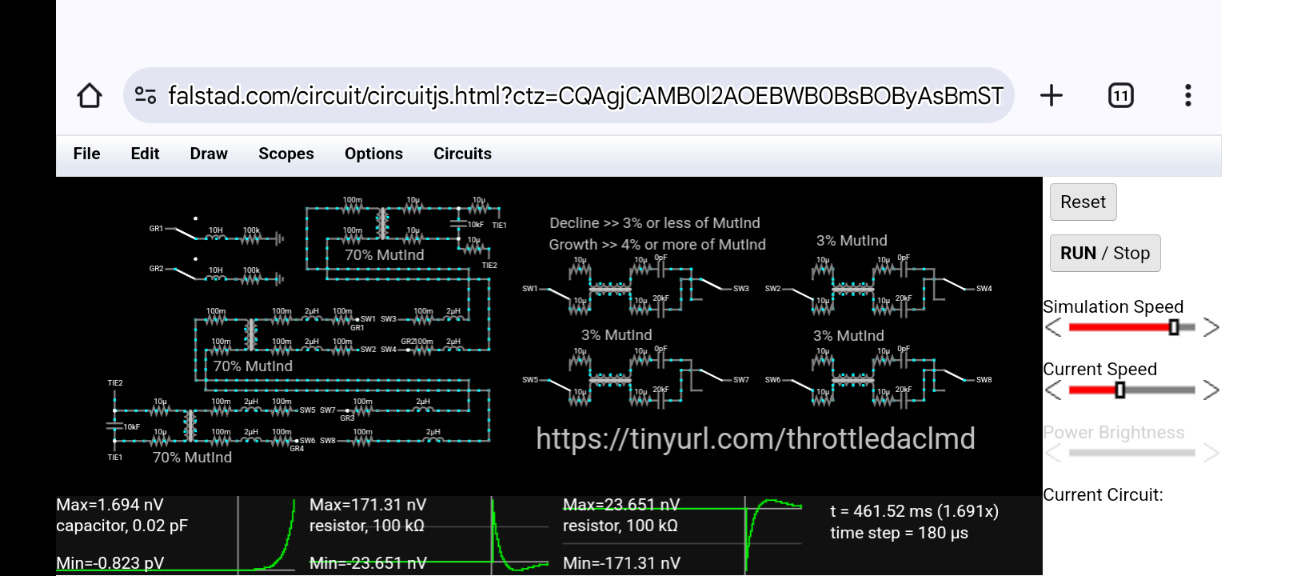
Escalating at an exponential rate towards infinite gain…

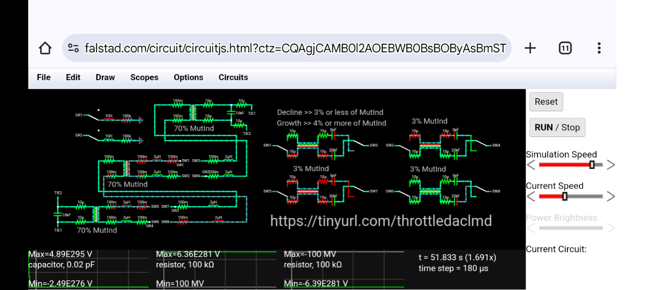
The limit of the simulator is reached which it calls infinity or just shy of it...! All three virtual oscilloscope tracings of voltage measurements become horizontal plateaus beyond which the simulator refuses to go any higher!

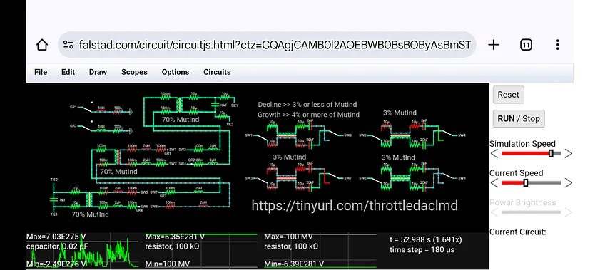
In the next image, I have reduced the mutual inductance to 3% within the transformer in the upper left corner of the foursome on the right hand side of this screenshot. That causes a severe drop in the voltage buildup within the capacitor as noted in its oscilloscope tracing to the far left. Meanwhile, the two resistors associated with the inductive heating element loads, located in the upper left corner of the schematic, undergo a voltage spike as noted in their tracings below…

The tracings of the 2nd and 3rd voltages level out to a nice stable outcome which gradually declines well the first voltage measurement on the far left continues to drop to some unknown value...
Finally, the bottom is reached on the first tracing to the far left and we see it's anything but stable. But that's because it's an individual component within this free energy circuit and there's no incentive for it to boost power. So, it exhibits randomized chaotic behavior which we would have seen had we microscopic vision during the buildup period. That wasn't obvious (during the build-up period) to see that chaotic behavior, but we can see it now very readily.
Chaos is intrinsic to free energy. If we know how to manage it without too tight a grip, then we can achieve what we want provided we exercise a good deal of dexterity in the process since this is no simple-minded flashlight circuit that we are dealing with. Instead, these types of circuits require a good deal of intelligence practically bordering on artificial intelligence of an analog type rather than the digital type of artificial intelligence that we are increasingly becoming accustomed to.
This older style of artificial intelligence dates back to a century ago long before the digital age commenced upon our collective psyche. Such giants of electrical engineering, such as Nikola Tesla and Charles Steinmetz, were pivotal in engineering artificial intelligence into their knowledge of electrical circuitry.
But now we have to rely on more recent giants of electrical engineering, such as Eric P. Dollard, Jim Murray, Paul Babcock, and several others who have graced our planet in more recent years. I study under these giants, because it's easier since they're closer to my generation. Whereas, people a century ago are pretty much outside of my attention span (for the most part), because they spoke a different language and they lived a different life. Everyone did back then.
🌈