


How to Build an Ideal Transformer

As I stated in a previous post,...
“… reactive components are not fence sitters…”
“Their output cannot equal their input”
Conservation of Energy cannot relate to Idealized Components

Reactive components are not “fence sitters”. They are not capable of maintaining the consequences of their reactions especially if they are ideal (incapable of losing energy).
But because electrical engineers are paid to lie to themselves on the presumption that all electrical circuits that they ever encounter will always have real power dominating over imaginary power to such a degree of emphasis that the conservation of energy is assumed to be upheld on the presumption that it is true and when executed encourages electrical engineers to feed their circuits more than enough power to run them. This reinforces the LIE (that they get paid to uphold) since they will only get the results that they expect to get. Namely, it will be a self-fulfilling proposition to feed circuits more energy than they need to run themselves and thus automatically it will be self-evident, supposedly, that the conservation of energy is a law all of the time when in fact it is merely a self-fulfilling proposition.
Furthermore, I have already discovered and shared with you what I learned from artificial intelligence…
Are you willing to lie for your country?

If you can lie to yourself and everyone else that 2 + 3 does not equal 5, then we will pay you to become an electrical engineer. And you can face your wife and your family with a big grin on your fac…
…that electrical engineers are also paid to lie to themselves concerning the computation and calculation of the total power, namely the complex power, of their circuitry by fudging the results by throwing away the imaginary component of reactive power and assume it to be real power for the purposes of summation of squares according to the Pythagorean theorem which is applied to the calculation of the total power of an electrical system.
Resistance versus Reactance

In the following dialogue between myself and A.I. over at Bing Copilot, it takes a long time for me to realize that A.I. has made a mistake and in what manner has the mistake been made. But to its cr…
This works well enough with very little deviation from accuracy (again) on the presumption that all electrical circuits will be fed more than enough energy than it takes to run their loads.
But what if a circuit is not given adequate energy to run its load? What if an electrical circuit is starved, yet, fed something (but not enough – far from enough) to run its load? What then?
A secret leaps out of a mysterious field of ignorance to which all electrical engineers are programmed to persevere in. Namely, the over-reactance of reactive components in fulfillment of Foster's reactance theorem producing negative impedance.
This is not entirely true because impedance never changes its polarization. It never turns into negative impedance. It always remains positive impedance.
This misunderstanding, among electrical engineers, is due to the fact that what changes polarity is not impedance, but is the reactive voltage of a version of Watt's Law that is rarely focused upon. Namely, that power equals real voltage input times imaginary voltage output divided by inductive impedance and capacitive impedance and resistance and all of this within a framework of time making Watt’s Law an artistry of fiction oversimplifying the fact that (in reality) we are describing what should be called Joule's Law for the production of energy within a framework of time and inclusive of electrical reactance.
This is the circuit's attempt to make up for the lack of energy supplied to run its loads. This will only occur if the circuit is severely starved, not mildly starved, of input power.
So, the secret definition of an ideal transformer is not a transformer which fails to lose any of its magnetic or dielectric energy. In reality, the definition of an ideal transformer is a generator of power because, as stated above, reactive components are incapable of stable behavior. Their output must not coincide with their input or else they would fail to be reactive. Instead, they would be similar in their behavior to resistors. In fact, they would be resistors and they would not be anything else.
Now, we get to the good stuff …
How to build an ideal transformer.
All credit goes to Byron Brubaker for the insight that I'm about to share with you. It stems from my conversation with him after I posted my data concerning my simulation of the Joseph Newman motor in LTSPICE failing to behave as Joseph Newman directed people to build it as written up in Joseph Newman's book, 8th edition.1
Parasitic oscillations will occur in an electrical circuit devoted to the correct arrangement of capacitors and coils of wire and fed a scarcity of energy. These parasitic oscillations possess a frequency which is elevated above whatever frequency you expect the circuit to operate under conventional circumstances because you are no longer operating in that realm.
Please see the midsection of my post on the topic of Tesla's patent for the production of radiant energy for a simulated example of how to regulate the frequency of these parasitic oscillations and, thus, regulate the amplitude of their output.
Apparatus for the utilization of radiant energy, by Nikola Tesla (1901).

Inventors have been known to leave information out of their patents since they're trying to make a living.
This was what was missing in Joseph Newman's version of his device which Byron Brubaker modified by suggesting to Joseph that he remove the permanent bar magnets, acting as a rotor, and replace them with dielectric canisters of helium whose exterior surfaces are wrapped with a single open coil on each canister which is not shorted to itself nor connected to anything else. Joseph Newman hid this secret by painting the exterior surface of these canisters with a dark color to hide what they were and to make them look more like rusty iron bar magnets since he painted them brown as in the picture at the top of my post at Quora linked-to above.
Transformers have an uncanny ability to operate due to the fact that they sacrifice their ability to operate at high frequencies by possessing an iron core - something which air core coils do not possess.
This iron core enhances the performance of a transformer yet makes it impossible for it to operate as an ideal transformer because it is only elevated frequencies that will give over unity results.
Thus, my suggestion to you, is to build an ideal transformer by throwing away it's iron core and replacing that iron core with a dielectric canister filled with a noble gas, such as helium or argon or whatever, and wrapped with one or more open coils.
On top of this substrate is wrapped the primary and secondary of a conventional transformer winding. This will achieve over unity as has already been demonstrated by the modifications made to the Joseph Newman motor suggested to him by Byron Brubaker.
The noble gas (within the interior of the dielectric canister acting as a substitute core for an ideal transformer) will produce an elevated frequency of electromagnetic fields capable of contributing to the electromagnetic fields of the primary and secondary windings of that transformer and make it possible for this type of transformer to become an over-unity component.
The noble gas will behave this way because the open coil wrapped around its dielectric vessel will pick up the voltage of the dielectric fields surrounding the primary and secondary windings of this transformer and transfer this to the noble gas inside this canister.
Although Joseph Newman never gave Byron Brubaker the credit, claiming that God gave Joseph Newman this secret advice, Joseph did hint to the general public how he performed this miracle by claiming that the atomic structure of the copper winding always acts as a perpetual motion machine in the form of a perpetually spinning gyroscope.
This is true in as much as the atoms of noble gas are spinning in a perpetual manner. Unfortunately, the orientation of their spin axes are so different from one another that on a macroscopic level it all evens out to a zero gain. Joseph Newman overcomes this by placing an open coil around the dielectric vessel containing this noble gas. This open coil will orient the spin axes of all the atoms of noble gas into a parallel arrangement causing the collective result to be a viable gain instead of a neutralized waste of time.
This collective alignment of all of the spin axes of all of the atoms of noble gas is analogous to how a permanent magnet is made in the first place.
Remember the permanent bar magnets that Byron had Joseph remove?
These permanent bar magnets are manufactured by immersing them within a very strong magnetic field while their magnetizable material is still hot and capable of its atoms and molecules migrating around within its interior. Then, the temperature is reduced to allow this hot pliable material to solidify. Once solidification has completed itself, the magnetic field is reduced to harden the parallel arrangement of all of the magnetized molecules making up the formation of this brand new permanent magnet.
Now, wasn't that easy?
😲
Update
https://tinyurl.com/electretneonidealtrannycore
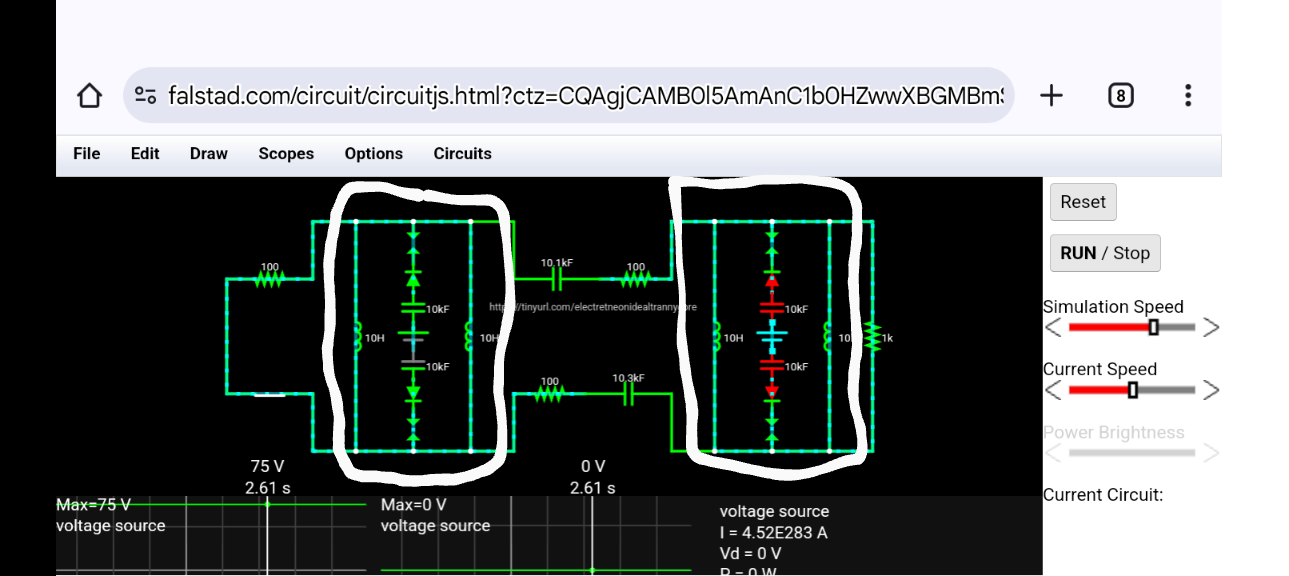
Two hypothetical ideal transformers, constructed from off-the-shelf equivalent parts, are circled in white marker in the screenshot, above, and posted to GitHub…
Ideal Transformer discussion at GitHub

Question asked of Google AI – Are spark gaps capable of generating DC current? Especially if they are neon bulb type spark caps?
Its answer plus my commentary ...
While a spark gap can conduct current, it's not designed to generate DC current, and neon bulbs are not suitable for this purpose. Spark gaps are typically used for transient voltage protection or switching high voltages, not for DC generation. [1, 2, 3]
Commentary for first footnote – we don't have to worry about electrodes melting (as mentioned in that Quora answer), because we don't use electrodes in our ideal transformer. In fact, nothing goes inside of the dielectric canister serving as the core of an ideal transformer except a noble gas such as neon or helium. On the outside, wrapped around this dielectric canister, is an open coil serving as our substitute for what would otherwise be a pair of electrodes on the inside. A pair of electrodes would have polarized the voltage charge within the dielectric canister along the geometry of a dipole, but an open coil will achieve the same effect. Also, we are not trying to achieve high voltage arc discharges such as what footnote number one indicates is the purpose of a spark gap. Instead, we are trying to achieve that mild glow of neon gas within our dielectric canister because all we have to do is slightly energize the internal gas in order to get it to broadcast an electromagnetic frequency within a minimum frequency of a few thousands of cycles per second up to a limit of around 200,000 cycles per second. That's it! Any achievement greater than this is excessive and unnecessary for producing over unity in an ideal transformer core designed for that purpose. So, don't try to use conventional wisdom when analyzing Byron Brubaker's suggestion to Joseph Newman on how to make improvements to the Newman device, [A] because that conventional wisdom will not be applicable.
[2] https://electronics.stackexchange.com/questions/540568/can-you-turn-ac-into-dc-through-a-spark-gap
[3] https://en.wikipedia.org/wiki/Spark_gap